Introduction
While developing a recent ESP32-based project, I needed to integrate an Analog / Maxim / Dallas DS18B20 digital thermometer. There are plenty of existing libraries that implement the 1-Wire communications protocol and DS18B20 commands, but most rely on bit-banging to generate the required signal timings.
Bit-banging implementations typically disable interrupts and toggle GPIO pins with microsecond-scale delays between operations. Although these delays are short—typically 60 µs to 120 µs per bit—they add up quickly when reading multiple bytes from several sensors. During these waits, the CPU is essentially busy-waiting, delaying interrupt handling and preventing higher-priority tasks from running.
To reduce CPU overhead and improve timing accuracy, I explored whether the 1-Wire protocol could be implemented using a hardware peripheral, ideally still communicating through a single pin.
As it turns out, Analog Devices published an article back in 2002 describing exactly this technique: implementing a 1-Wire host interface using a UART. The concept still applies perfectly to modern microcontrollers such as the ESP32. Analog’s original article is available here and summarised below.
Electrical Interface
The typical configuration of a 1-Wire bus is as follows:
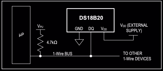
A typical 1-Wire bus consists of a single data line and ground, with a 4.7 kΩ pull-up resistor holding the bus high when idle. Communication occurs when either the host or a device pulls the line low using an open-drain or open-collector output.
Analog’s article included buffer circuits for connecting a UART with a push-pull output to a 1-Wire bus. Fortunately, the ESP32’s flexible I/O configuration allows the UART TX pin to be configured in open-drain mode, eliminating the need for an external buffer. It also allows both TX and RX signals to be mapped to the same pin, perfectly matching the required 1-Wire electrical interface.
1-Wire Signalling
The 1-Wire protocol, originally described in the Book of iButton Standards, defines several basic signals:
- Reset / Presence — Initializes the bus for a new transaction. After reset, devices respond with a presence pulse to announce themselves.
- Write “0” — Sends a logic-0 bit.
- Write “1” — Sends a logic-1 bit.
- Read — Samples a bit (0 or 1) from the bus.
Reset / Presence
An example of the reset/presence signals is as follows:
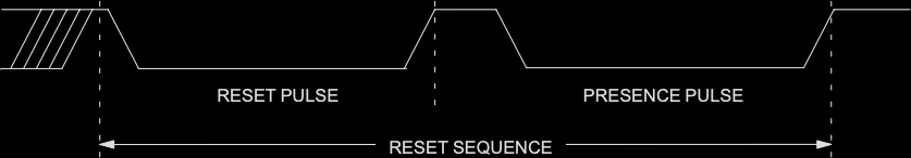
To issue a reset, the host pulls the bus low for at least 480 µs, then releases it. Each device responds by pulling the line low for 60–120 µs, after a delay of 15–60 µs, to signal its presence.
Analog’s method reproduces this signal using a UART configured at 9600 bps.
At that rate, each bit is 104 µs long, and a 10-bit UART frame (start bit, 8 data bits, stop bit) lasts about 1.04 ms. Transmitting the byte 0xF0 generates the required waveform: the start bit and four 0-bits create the ~480 µs low pulse, while the remaining bits provide the high period for presence detection.
Because TX and RX are connected, the transmitted frame is also received. If the received byte differs from the transmitted one, at least one device has pulled the bus low during the presence window—indicating that a device is present.
Write “0” / Write “1”
Examples of a zero or one being written to the bus is as follows:
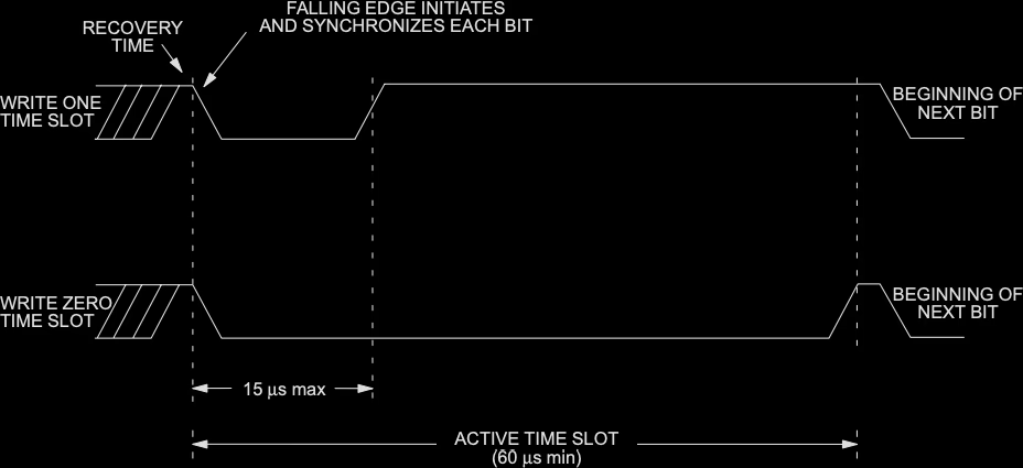
Each bit is transmitted during a defined time slot.
- A “1” is written by pulling the line low for ≤ 15 µs and then releasing it. Devices sample the bus between 15 µs and 60 µs after the falling edge.
- A “0” is written by keeping the line low for the full slot (60–120 µs).
Analog’s implementation uses a 115200 bps UART, where each bit lasts 8.6 µs.
Transmitting 0xFF for a “1” and 0x00 for a “0” produces the correct timing, with each slot lasting approximately 86 µs (10 bits × 8.6 µs).
Read
An example of a bit being read from the bus is as follows:
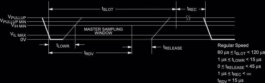
A read operation begins like a “1” write: the host pulls the bus low for 1–15 µs, releases it, and then samples the bus after a short delay. Devices transmit a “0” by pulling the line low during the sampling window, typically 15 µs wide.
Using a UART at 115200 bps, the host transmits 0xFF and inspects the received byte:
If it differs, a device pulled the bus low (bit = 0).
If the received byte matches 0xFF, the line stayed high (bit = 1).
ESP-32 Implementation
To test this approach, I developed a UART-based 1-Wire driver and a separate DS18B20 library built on top of it. Together, they form a simple example firmware project for the ESP32 family, built with PlatformIO and tested on an ESP32-C3.
The example firmware:
- Configures the UART-based 1-Wire bus.
- Scans for connected devices and prints their unique ROM IDs.
- Periodically requests temperature readings and prints the results.
It also supports adjusting the DS18B20’s resolution to reduce conversion time—from 12-bit (750 ms) down to 9-bit (94 ms).
However, not all sensors support changing resolution. During testing, my batch of low-cost DS18B20s appeared locked in 12-bit mode—a tell-tale sign of clone devices. (Lesson learned: bulk bargains often come with surprises! 🙈).
The PlatformIO based example project can be found here.
The DS18B20 library, which can be found here.
The UART based 1-Wire library can be found here.
A typical output from the example, showing two sensors being detected and sampled would be:
I (489) MAIN: Found device ROM code: 28FF640E7D249B67
I (489) MAIN: .Device is a DS18B20 temperature sensor
I (529) MAIN: Found device ROM code: 28FF640E7F3C4807
I (529) MAIN: .Device is a DS18B20 temperature sensor
W (619) MAIN: Failed to set resolution for DS18B20 [0]
W (699) MAIN: Failed to set resolution for DS18B20 [1]
I (699) MAIN: Performing individual temperature conversions and readings
I (789) MAIN: Temperature [0]: 19.06 degC
I (869) MAIN: Temperature [1]: 18.94 degC
I (1369) MAIN: Issuing simultaneous temperature conversion to all DS18B20 devices
I (1439) MAIN: Temperature [0]: 19.06 degC
I (1469) MAIN: Temperature [1]: 18.94 degC
The “Failed to set resolution” messages above are a consequence of the clone devices used for testing.
Conclusion
This project demonstrates an alternative way to communicate with 1-Wire devices—using UART hardware rather than traditional bit-banging. The result is a more efficient, interrupt-friendly approach that preserves real-time responsiveness for other peripherals such as Wi-Fi, while reclaiming valuable CPU cycles otherwise lost to busy-waiting.
Leave a Reply