Introduction
I rarely get to share what I’ve been up to recently with my clients, what with NDAs and the like. Recently I was asked to develop the software for a product featuring Controller Area Network Flexible Data-rate (CAN FD) controllers. This post details the slightly meandering route I took to getting a CAN FD network up and running between my development machine and customer’s development boards.
CAN and CAN FD
The Controller Area Network (CAN) bus was originally developed as a vehicle bus standard. Allowing for the various control units in a vehicle to exchange messages with each other over shared wiring. Thereby reducing the cost and weight of the wiring loom. Today it continues to be used widely in vehicles while seeing usage in other areas, such as industrial automation and elevator control systems.
CAN was originally developed by Bosch, with the CAN 2.0 standard, released in 1991 being the most widely used. In 2012 Bosch released the CAN FD 1.0 standard, the next generation of the interface. Messages (frames) on a CAN 2.0 bus consist of an address/identifier (either 11 bits, in the case of CAN 2.0A or 29 bits in the case of CAN 2.0B) followed by up to 8 data bytes. Both the address and data on a CAN 2.0 bus are transmitted at the same bit rate, up to 1Mbps. CAN FD as the name suggests has a “flexible” data rate, allowing the bitrate to be increased to up to 8Mbps (although 5Mbps is more typical) during the data transfer phase of a message. While remaining at a maximum of 1Mbps during the address transfer (arbitration) phase of a transmission. Additionally CAN FD supports longer messages, with the 8 byte limit of CAN 2.0 being increased to 64 bytes for CAN FD 1.0.
The Adventure Begins
I’ve worked extensively with the CAN 2.0 standard in the past. Development boards and USB interfaces are readily available from low cost hobbyist units to high end validation tools. I’ve built up a small collection of these over time. However digging through my collection at the start of this new project I found that I didn’t have any development tools supporting CAN FD.
A typical microcontroller CAN bus interface would be arranged as follows:
Within each control unit on the bus, a microcontroller communicates with the other nodes on the bus with the help of a CAN controller and CAN transceiver.
The controller may within the microcontroller, connected directly onto one of its internal busses. Or external, connected for example via a serial peripheral interface (SPI) bus. It’s responsible for implementing the CAN protocol, receiving and transmitting frames on the bus on behalf of the microcontroller.
The transceiver handles the physical layer of the network. Providing translation between the single ended transmit and receive lines of the CAN controller and the physical layer implementation in use. Typically for vehicle CAN busses this is a two wire differential bus.
For CAN FD both the controller and transceiver are new. New controllers are required to implement the new protocol. While new transceivers are required to support the increased bitrate of CAN FD.
CAN FD Transceivers
My customer’s microcontroller had been deliberately selected due to its built-in CAN FD controllers. Therefore it only required external transceivers to join a CAN FD bus.
Low cost development boards are readily available for the CAN 2.0 standard, such as this example based around the Texas Instruments SN65HVD230 transceiver IC.
However breakout boards which feature a CAN FD transceiver seem to be few and far between. I initially considered attempting to find a pin compatible CAN FD transceiver and transplanting it onto a donor CAN 2.0 breakout board. But ultimately decided it would be quicker and easier to just design my own tiny breakout board with the required transceiver.
USB to CAN FD Interface
Hardware
With the transceiver breakout boards produced the customer’s development board could now join a CAN FD bus. Next I needed a CAN FD compatible device to communicate with. This would ideally be a desktop computer, allowing for test harnesses to be run against the unit.
I’ve previously used Peak Systems PCAN-USB adapter to provide access to CAN 2.0 networks. They offer a CAN FD capable adapter in the same product family…..however it’s quite a bit more expensive than the CAN 2.0 model….and I’d need a few of them 😅.
In my collection of CAN bits and pieces are several low cost adapters. These adapters are typically built around STMicroelectronics STM32 family of microcontrollers. Some of which include USB and CAN controller peripherals.
Typically it seems that the STM32 F0 and F4 family are used. The few adapters in my collection contain STM32F072 parts, however these only provide a CAN2.0 controller. I therefore designed a board around the STM32G0B1, which includes a pair of CAN FD controllers as well as the required USB controller.
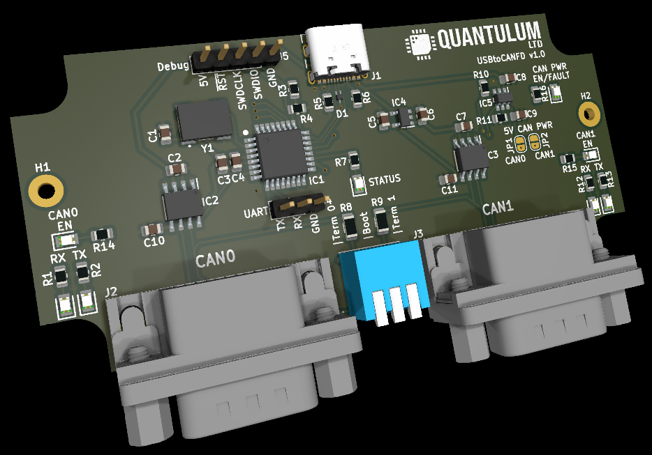
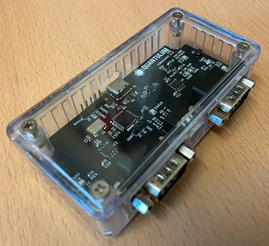
Which assembled into an off the shelf enclosure with a few milled slots becomes.
Firmware
Project Selection
From my experience with previous low costs adapters, while they may be running different firmware images, they are typically supposed by the Linux driver “gs_can”. This driver was developed for a USB to CAN interface produced by the now defunct “Geschwister Schneider Technologie-, Entwicklungs- und Vertriebs UG” company. It appears to have become a de-facto standard interface to a range of USB to CAN interfaces.
Several open source firmware projects exist which implement this driver. One such project is candlelight_fw which support a series of units based around the STM32 family. I’ve had success running this firmware on other adapters, although it currently only officially supports the STM32 F0 and F4 families. There were mentions in the repository of upcoming support for the STM32 G0 family however it’s noted that this is currently incomplete.
I continued my search for firmware supporting the gs_usb driver and found budgetcan_fw which explicitly mentions support for the CAN FD peripheral in a number of the STM32 families as well as supporting the gs_usb driver.
I followed the excellent documentation provided in the readme and got my new adapter up and running.
Using tools from the can-utils package it passed some basic tests.
With a pair of adapters connected to the PC I gain network interfaces can0/can1 and can1/can2. Linked by a short CAN bus cable, they can be configured for CAN FD use and brought up as follows. Here providing a CAN 2.0 (nominal) bitrate of 1Mbps and CAN FD (data) bitrate of 8Mbps.
ip link set dev can0 type can bitrate 1000000 fd on dbitrate 8000000
ip link set dev can0 up

ip link set dev can2 type can bitrate 1000000 fd on dbitrate 8000000
ip link set dev can2 up
Once up we can monitor incoming frames on can2 with the candump tool:
candump -x can2
We can then send a series of test frames from can0 to arrive on can2 via the CAN bus, using the cansend tool.
Here we send a CAN2.0 frame, with the 11-bit ID 0x123, and an 8-byte payload. The ID and data bytes are separated by a hash.
cansend can0 123#0011223344556677
Here we send a CAN2.0 frame, with the 29-bit ID 0x123. Selecting a 29-bit ID is a simple case of providing 8 rather than 3 hex digits to cansend.
cansend can0 00000123#0011223344556677
Here we send a CAN FD frame, with 11-bit ID 0x123. CAN FD is selected by providing two hashes instead of one between the ID and data. Additionally we must provide a flag selecting the CAN FD options. Here the flag presented is 0x0. Data bytes can be separated by a period, which here has been used to separate out the CAN FD flags.
cansend can0 123##0.0011223344556677
The above example sends a CAN FD format frame, but doesn’t request a bit rate switch, such that the data bytes will be transmitted at the configured nominal bitrate of 1Mbps. To have a bit rate switch performed and therefore the data transmitted at the full 8Mbps, we provide the bit rate switch flag value of 0x1. The supported flag values can be found in the Linux kernel source.
cansend can0 123##1.0011223344556677
We can see the differences between each of these transmissions in the output of candump:
phil@phil-ultrabook:~$ candump -x can2
  can2  RX - -  123   [8]  00 11 22 33 44 55 66 77
  can2  RX - -  00000123   [8]  00 11 22 33 44 55 66 77
  can2  RX - -       123  [08]  00 11 22 33 44 55 66 77
  can2  RX B -       123  [08]  00 11 22 33 44 55 66 77
Not shown above is a CAN FD transmission with bitrate switching and extended (29-bit) addressing selected at the same time.
Firmware Issues
I found one small issue early on when using the firmware, CAN FD didn’t work at high speeds. For example selecting an FD data rate of 2Mbps worked, but 4Mbps or higher didn’t. The solution to this turned out to be enabling the transceiver delay compensation feature of the CAN controllers. During normal CAN transmissions the controller drives the TX line, while monitoring the RX line. This allows it to ensure that the bit its attempting to place onto the bus hasn’t been destroyed by another node driving the bus at the same time. This is particularly important during the address transmission (arbitration) phase of a frame. During this phase multiple devices may be competing for access to the bus. One of the features of new FD capable transceivers is a lower TX to RX delay required to support the higher bit rates. However as this delay varies between devices it’s possible to request that the controller apply a small delay before sampling and checking the transmitted bit.
With the basics working I looked to prove the correctness of the adapters. That all the messages send were received and vice versa. For this I used the can-utils took canfdtest. Here the fd stands for full duplex, one unit sends a message to another running the same tool. Which increments each data byte and replies on a different CAN ID.
I initially used the version included in my distributions package manager, until I found it didn’t have any CAN FD support. It seems however that building the tool directly from the upstream project isn’t too involved.
wget https://raw.githubusercontent.com/linux-can/can-utils/46fae98b769353279df9d591ca9dd44c2e3cf76d/canfdtest.c
gcc -o canfdtest canfdtest.c
Testing between two adapters as before, in one terminal we request the tool listen for and respond to messages:
./canfdtest -v can2
In another we request the tool generate messages and check the responses received:
./canfdtest -v -g -l 10000 can0
By default the tool uses CAN 2.0 messages with length of 8 bytes. Adding -v causes the tool to be a little more verbose and show its progress. Adding -l limits it to sending a certain number of frames, else it continues until stopped.
We can perform a similar test using CAN FD messages, with bit rate switching and the maximal message length of 64 bytes as follows. In one terminal:
./canfdtest -v -b -d -s 64 can2
In another terminal:
./canfdtest -v -b -d -s 64 -g -l 10000 can0
This is where things took a turn for the worse. The CAN 2.0 test would pass without issue. The CAN FD test would pass with a data length of up to 48 bytes. But a CAN FD test with 64 byte frames would result in data corruption. This corruption would appear in the form of a missed byte. The corruption wouldn’t appear immediately either, it was always generally on the 16th transmission…..which appeared suspiciously like some sort of queue wrapping / overwriting issue.
The sequence of actions being performed by the pile of broken hardware on my desk is largely:
Application -> Linux Kernel (gs_usb driver) -> USB -> STM32 USB (gs_usb device driver) -> STM32 application code -> STM32 CAN -> CAN -> STM32 CAN -> STM32 application code -> STM32 USB (gs_usb device driver) -> USB -> Linux Kernel (gs_usb driver) -> Application
The reverse route is of course symmetric, with the reply generated by the canfdtest application following the same route back to the original adapter. Something, somewhere in there is broken 🙈.
Getting the debugger involved could be a pain as stopping the processor for too long would likely cause the USB to disconnect. So instead I resorted to the trusty old print statement. Dumping the inbound and outbound frames in one of the controllers. As it happens this made things far worse. The delay introduced while dumping a frame over the UART appeared to cause the inbound frame queue from the USB to overflow. The queue overflow appeared to be caused by always starting a new USB receive transfer, regardless as to whether the last received message filled the queue. Rather than applying back-pressure, by holding off on future USB transfers, preventing the desktop PC from sending until there was more queue space.
Along with the discovery above I found a few other oddities. The software was using the realtime operating system FreeRTOS. Given its simple task of moving messages between CAN and USB this seemed excessive, with three tasks being switched in and out. However it appeared to be using the queuing API provided by FreeRTOS appropriately. It generally looked quite sensible and was easy to follow. Apart from some slightly suspicious task delays with hard coded zero durations. Safe to say fixing it wasn’t going to be as quick as I’d hoped.
Taking a step back and looking at the files in more detail, it appeared that at least some of them had been adapted from the candlelight_fw project. It was at this point I found the classic tangled web of open source pull requests, branches, and repositories. The owner of the budgetcan_fw repository had open pull requests within the candlelight_fw repository looking to add support for the STM32 G0 family. It appeared he may have been working on his own firmware at the same time and appears to have put a great deal of effort into getting things going (great work by the way Ryan). Some time later the other developers working on the candlight_fw project had picked up and continued his work. From this I was able to adapt and build images based on the candlight_fw project and another open pull request 🙈. Which having integrated the same automatic transceiver delay compensation fix passes all the tests, running for several hours without issue. Transferring millions of CAN FD frames, with bit rate switching at 8Mbps 😁.
Performance Testing
While performance isn’t super important for my initial use case, I thought it might be interesting to test while everything was hooked up.
I considered measuring performance using two metrics. Maximum number of frames per second. For this the smallest CAN frame would be transmitted, using an 11-bit ID with no data. Along with maximum bus load, sending the largest frames. For example for CAN 2.0 with a 29-bit address and 8 byte of data. Or a CAN FD frame with a 29-bit ID and 64 bytes of data.
can-utils provides, cangen which can generate and send large volumes of CAN frames. Along with canbusload which given a CAN bitrate will receive incoming frames and with knowledge of the CAN protocol calculate the current load on the bus.
Ideally we should be able to hit 100% load at the maximum bitrate with both the largest and smallest messages. The smallest messages resulting in the highest number of frames being transmitted. While the largest messages result in the highest data throughput.
We can have cangen generate random 11-bit IDs, with no payload on one bus.
cangen -g0 -i -x -L0 can0
While monitoring the apparent load on the other.
canbusload -e can2@1000000
This results in the following output:
 can2@1000000  6958  340637      0  34%

 can2@1000000  6919  338730      0  33%

 can2@1000000  6971  341352      0  34%

 can2@1000000  6925  339049      0  33%

 can2@1000000  6903  338122      0  33%
Repeating the test with 8-data bytes and 29-bit IDs:
cangen -g0 -i -x -L8 -e can0
Results in the following output:
 can2@1000000  6192  836107 396288  83%

 can2@1000000  6352  857686 406528  85%

 can2@1000000  6522  880637 417408  88%

 can2@1000000  6441  869916 412224  86%

 can2@1000000  6148  830244 393472  83%
Seems we can send nearly 7000 msg/s with 11-bit IDs and no payload and just over 6000 msgs/s with 29-bit IDs and 8-byte payloads. Loading the bus to a maximum of 86%….not bad.
Performing the same test with CAN FD becomes a bit trickier as canbusload doesn’t currently support CAN FD.
We can request cangen transmit CAN FD frames using the -f argument.
Repeating the 11-bit ID / zero length payload test becomes:
cangen -g0 -i -x -L0 -f can0
As an approximation / dirty hack it occurred to me that I could measure the rate at which candump was outputting lines, as it presents each can frame on its own line. Here we pipe the output of candump into pv, a pipe progress monitor. Asking it to calculate the current and average rate of data through the pipe in lines per second. Giving us CAN frames per second:
candump -x can2 | pv --line-mode --rate --average-rate > /dev/null
After running for a few minutes the output stabilised at:
phil@phil-ultrabook:~$ candump -x can2 | pv --line-mode --rate --average-rate > /dev/null
[5.44k/s] [5.46k/s]
Averaging 5460 msgs/s.
Switching again to the other extreme, using 29-bit IDs, 64-byte messages and enabling data bitrate switching (with -b):
cangen -g0 -i -x -L64 -b -e can0
We see a new average from the candump / pv pipeline of 4990 msg/s.
I’m quite happy with those results, and given speed isn’t the name of the game this adapter will serve my need just fine.
Conclusion
In retrospect, I probably should have just bitten the bullet and grabbed a load of off-the-shelf adapters. However I’ve now got company branded CAN adapters 🎉 . While having learnt a lot more about CAN FD than may have otherwise done if everything had just gone well. Luckily my customer didn’t need their software in a great rush.
Development Notes
The candlelight_fw firmware supports the ethtool identify command, which when executed will cause the lights of the interface to blink, helping to identify the adapter:
ethtool --identify can0
Increase the kernel transmit queue length for the controller from the default of 10 to something bigger:
ip link set dev can0 txqueuelen 1000
Leave a Reply