Introduction
Having got LTE working with Analog’s ADALM-PLUTO SDR several readers requested I get it working with a variant of the Pluto, the Pluto+.
I was aware of the Pluto+ when starting my original project but decided to go down the official Analog route. In part because I suspected there were more Analog devices in the wild and sourcing them would likely be easier. But mainly due to Analog’s excellent documentation. If I needed to get something working I suspected they’d already have a wiki page on it. Which so far has proven true.
The Pluto+ appears to have been developed by Jun Su and Howard Su, based on the contributors list of the unit’s Github repository. Its manufacturer has proved largely a mystery, but it’s for sale on AliExpress 😀. Having ordered one, it appears to be relatively well built. With the GitHub repo supplying the appropriate technical documentation to explain the differences to the official Pluto.
This post covers getting LTE working on it. Making use of it’s party piece over the Analog ADALM-PLUTO, the addition of an Ethernet interface. Not support for a USB to Ethernet adapter as offered by Analog’s device, but access to the Gigabit Ethernet controller built-in to the Xilinx Zynq system-on-chip powering both devices. A full 1000Mb of fun.
Pluto+ vs Analog ADALM-PLUTO
The Pluto+ and Analog ADALM-PLUTO are very similar, both being based around Analog’s AD9363 RF Transceiver, paired with Xilinx’x Zynq 7010 hybrid FPGA/CPU platform.
The designers of the Pluto+ made several tweaks to the original Analog design.
These include:
- Migration from a 25ppm oscillator to a 0.5ppm voltage controlled temperature compensated crystal oscillator (VCTCXO). No more hardware mods or external clock sources required to achieve the accurate timing needed to support LTE.
- Addition of a Gigabit Ethernet interface, with required physical interface, and magnetics. Potentially increasing data throughput to the unit.
- Addition of microSD card slot. I’ve not used it yet, past checking it works. In future it may be used for booting the unit, as an alternative to the onboard QSPI flash. For example if a larger OS image is required. It’s more likely to be used for external mass storage.
- Addition of SMA connectors for the additional RF channel. Analog’s Rev D Pluto provides access to the second TX/RX pair provided by the transceiver. Although this is via IPEX connectors, requiring an (all be it small) hardware mod to make use of. Pluto+ makes accessing both channels easy, providing dedicated SMA connectors.
In many ways the Pluto+ is what the original Analog ADALM-PLUTO should have been in my opinion. But I see what they were aiming for, a low cost (for an SDR) platform for learning and experimentation. Rather than something with unnecessary bells and whistles, that would be overkill for their primary goal, while increasing costs.
FPGA Hosted Hardware Updates
The Pluto+ essentially runs exactly the same FPGA image as the original Pluto. With only a few minor changes. The pin allocations of the Zynq needed to change. The Pluto+ uses a different Zynq package than the original Pluto. Thankfully the patches provided by the original developers still just about apply so this was covered easily. Enabling of the Ethernet controller and SDHCI controllers before configuring their signal routing. Tweaking the allocation of a signal which would otherwise conflict with the USB controller. More on that later. (there’s a physical jumper that may need moving on your board).
For more information on the FPGA tweaks, see my original post.
Low Latency IP “Gadget” Daemon
While modifying the original Pluto, I found that the industrial input output (IIO) daemon, hosted by the unit for its USB and IP based communications wasn’t able to meet the latency requirements of LTE. It appeared to be designed to transfer large buffers of samples infrequently, rather than small buffers of samples frequently. As an example srsRAN will be requesting its RF samples in 1 millisecond blocks. Therefore the IIO daemon needs to provide 1000 of these blocks per second to the host from the receiver. While accepting 1000 blocks per second from the host for transmission.
In an attempt to be lazy I tried the IIO daemon again, this time over physical Ethernet, hoping it might perform better…..but alas, as before it fell on its face.
So similarly to the Pluto a new low latency, (hopefully) high performance version of the IIO daemon would be required. As with the USB version developed for the Pluto I chose to continue using the IIO daemon for the fiddly bits, configuring the transceiver for example. While implementing the data transfer mechanism myself, allowing the required latency and throughout targets to be met.
The new daemon is therefore based on the USB version developed for the Pluto. I briefly considered combining them as they perform largely the same task, just over different data transports. However they ended up different enough to warrant keeping them separate.
The basic flow is the same in both versions of the daemon. It makes use of a pair of threads. One reads blocks of samples from a network socket and writes them to the local IIO interface. The other does the opposite, reading blocks of samples from the local IIO interface and sending them via the same network socket.
UDP is being used as the transport protocol. Given the SDR will be connected over a local network (ideally a small local network, i.e. a minimum number of switches between the SDR and host). We don’t need the delivery and ordering guarantees that TCP provides. We can instead make some assumptions, for example that packets arrive in the order they were transmitted.
Standard Ethernet frames are limited to 1500 bytes, which taking into account an IPV4 header (20 bytes) and UDP header (8 bytes), results in a usable payload of 1472 bytes per packet. The smallest sample buffer size that will need to be transported over the network is 1920 samples. At 4 bytes per sample this results in a buffer size of 7,680 bytes. Therefore requiring 6 UDP packets to transfer.
For reception (RF -> host), after a few design iterations, the daemon makes use of the the sendmmsg system call. This call allows a full IIO buffer (all 1920 samples in the example above) to be split into individual packets. Each having a small header appended, containing details such as the position of the packet within the buffer and timestamp. Being sent in a single system call.
For transmission (host -> RF) a little more work is required. Ideally the recvmmsg call would be used, the counterpart to the call used above. Given the potential for the occasional packet to get lost, a single missing packet would knock the stream out of sync. Such that complete buffers would no longer be received. For now packets are received and processed one at a time by the regular recv system call. I did experiment with the recvmmsg call but there are other limitations which are hit before the system call overhead becomes a problem. I may be fun to implement a hybrid approach in the future with recvmmsg used to handle complete blocks whenever possible. With recv used to effectively discard blocks when required to get the stream back in sync.
SoapySDR Driver Updates
The SoapySDR driver extension for the Pluto version was further extended, adding support for the UDP transport, alongside the USB transport and original IIO transports.
See my original post for more detail on the original updates. The route I selected to update the driver adding timestamping support and the custom USB transport leant itself well to further extension. With the IP (UDP) transport, becoming a virtual mirror image of the code in the IP daemon above.
I have made a few slight tweaks / improvements to the driver. These include renaming the parameter to enable “direct” mode, from “usb_direct” to just “direct”. With the appropriate USB vs IP modes being selected based on how the Pluto+ is connected (the URI used for its connection). Although the old name remains for backwards compatibility.
Timestamping now also works if both channels are enabled and the test code has been updated to make use of both channels if requested. It seems I may have made a bit of a bodge in the original Pluto implementation, which I will be shortly checking/correcting. When the RF transceiver’s second channel is enabled its behaviour appears to change very slightly. I wasn’t making use of a signal deep within the FPGA, which indicates if a sample from the RF transceiver is valid (as I’d never seen it indicate that a sample wasn’t valid)…..turns out when two channels are enabled the valid signal becomes much more important. The result being that the timestamp counter was being incremented when it shouldn’t have been…..resulting in all the springs popping out.
Initially a puzzling problem, all became clear when I found that the Pluto+ ships with its second channel enabled, while the Pluto doesn’t.
Repositories
Various GitHub repositories have been forked in order to add timestamping support.
Analog ADALM-PLUTO Firmware – Top level repository which integrate the Linux kernel, Buildroot based root filesystem and HDL repositories. This repository may be used with the instructions from Analog’s wiki to rebuild the runtime and update images if required. At the time of writing the updates were based on the latest firmware release (V0.38). Despite its name the linked branch is a special formulated blend. Based on the original example provided by the developers, adding support for the integrated Ethernet controller and microSD card slot.
Analog HDL – Analog’s HDL repository. While no changes were required to the Analog HDL modules, the ADALM-PLUTO’s project required updates to integrate the new modules. A few additional tweaks are required to the project to add Ethernet and microSD support.
Analog Buildroot – Analog’s Buildroot repository for the ADALM-PLUTO. With the new low latency IP gadget daemon integrated as a custom package. Also along for the ride is the original USB gadget, such that the Pluto+ can support low latency timestamping over either its USB or Ethernet interface.
Pluto HDL Quantulum – New repository containing additional HDL modules. Included as a submodule in the top level firmware repository.
Pluto SDR IP Gadget – New repository containing the low latency IP “Gadget” daemon. Gadget’s a bit meaningless here sadly. Linux refers to its USB on-the-go (OTG) device support as “gadgets”….I shamelessly adopted it here (who doesn’t like gadgets?)
Pluto SDR USB Gadget – New repository containing the low latency USB Gadget daemon. This is the application used by the Analog ADALM-PLUTO, and remains usable on the Pluto+ while connected over USB.
SoapyPlutoSDR – Fork of the SoapySDR plugin for the Analog ADALM-PLUTO, with support for the low latency USB and IP daemons. Along with some example code demonstrating timestamping, primarily aimed at and used for testing.
Building
If you’re just looking to try, skip ahead to the next section. I’ve released some pre-built images on GitHub. The following notes are adapted from Analog’s wiki.
Building the Pluto+’s firmware requires installation of Xilinx’s Vivado Design Suite 2022.2. After which the firmware may be cloned and build as follows:
git clone --branch v0.38_plutoplus_timestamp --recurse-submodules --shallow-submodules https://github.com/pgreenland/plutosdr-fw.git
cd plutosdr-fw
make
Once complete (it takes a while) build artefacts will be available in the build directory. The two key images being pluto.dfu the RAM bootable image and pluto.frm the firmware update image.
Firmware Booting / Upgrade
Being based on the Analog Pluto, the Pluto+ includes the same options for booting the updated firmware. The following were adapted from Analog’s wiki.
If you’ve skipped ahead prebuilt images are available on GitHub, or you can build from source as described above if you prefer.
Booting from RAM
If you’re interested in testing the image before flashing it, you can boot the firmware from RAM using the device firmware update (DFU) mechanism.
For this the pluto.dfu file will be required, along with the dfu-tool, available in Debian and Ubuntu via the fwupd package.
- Enter DFU mode, by either:
- Allowing Pluto to boot, then connecting via it’s virtual serial console. Logging in with the username
rootand passwordanalog. Then issuing the commandpluto_reboot ramwhich will cause the device to reboot into DFU mode. - Removing the PCB from the case and holding the DFU button while connecting USB cable for power / data transfer (more a last resort on this unit).
- Allowing Pluto to boot, then connecting via it’s virtual serial console. Logging in with the username
- Having entered DFU mode, load and boot the image with dfu-tool. You may need to run these command as root to gain access to the USB device, or find/create the appropriate udev rules to set the device permissions correctly.
dfu-util -d 0456:b673,0456:b674 -a firmware.dfu -D pluto.dfudfu-util -d 0456:b673,0456:b674 -a firmware.dfu -e
- Once booted the device should re-enumerate on the host as a USB device with the name
Analog Devices, Inc. PlutoSDR+ with timestamp support, indicating that the new firmware has booted successfully.
Flashing
Having tested the image using the DFU booting method described above. If you’d like to flash it to the device the builtin mass storage based update method can be used. This method is exactly the same as the regular update process.
Simply drag and drop the pluto.frm file into the virtual mass storage device and unmount it. After which the LED on the device will begin flashing rapidly while the update is performed. Once the update is complete the device will reboot into the new firmware version.
If your Pluto+ is like mine, you may want to drop in boot.frm too which will update the first and second stage bootloaders. Mine shipped with a very early version. The version included matches the corresponding official release with support for the microSD card added.
The device should now always boot and enumerate with the new name Analog Devices, Inc. PlutoSDR+ with timestamp support. Indicating the firmware with timestamping support is installed.
Note: Remember not to disconnecting the USB while the LED is blinking rapidly, indicating the firmware update is in-progress as this risks corrupting the firmware.
If you with to return to the official Analog firmware at any time, the same mechanism may be used, with your chosen version of the official release
If updating the bootloaders you may want to restore the bootloader configuration to its defaults. This shouldn’t strictly be necessary, but there may be unexpected changes from the stock configuration. This can be performed using the uboot-env.dfu file. Unfortunately it can only be programmed using DFU mode. Enter DFU mode using the virtual serial terminal, executing the command plutoreboot sf. Once the device re-appears the u-boot bootloader environment can be reset with:
dfu-util -d 0456:b673,0456:b674 -a uboot-env.dfu -D uboot-env.dfudfu-util -d 0456:b673,0456:b674 -a uboot-env.dfu -e
Pluto+ Configuration
Once the new firmware is loaded or installed there isn’t any significant configuration required, the unit is pretty much ready to go out of the box.
Jumper Configuration
If you’ve only run the stock firmware on the unit, the internal hardware configuration should already be correct. However if you’ve switched from the original firmware to the Analog firmware for the ADALM-PLUTO you’ve likely moved a jumper inside the unit. This jumper setting is detailed in the original Github repo.
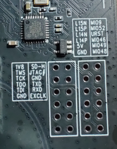
Shown without a header here, the right most row contains URST, MIO52 and MIO46.
For the Pluto+ specific firmware here, a jumper should be placed between URST and MIO46.
For the Analog ADALM-PLUTO firmware, a jumper should be placed between MIO52 and URST.
Static IP Address
I’ve assigned a static IP address to the Ethernet adapter of my unit, making it easy to track down. By default the adapter is configured to use DHCP.
A static IP can be provided by editing the config.txt file found on the virtual mass storage device presented when the unit is connected via USB. Updating the USB_ETHERNET section. Despite its name, this manipulates the hardware Ethernet adapter on the Pluto+. Presumably because a USB Ethernet adapter on the Pluto would appear as eth0, which is conveniently what the physical adapter in the Pluto+ appears as. A happy accident me thinks 😼:
[USB_ETHERNET]
ipaddr_eth = 192.168.1.100
netmask_eth = 255.255.255.0
Static MAC Address
If you’ve got multiple units, you may want to ensure that each unit has its own unique Ethernet MAC address.
There’s a mechanism in place in the bootloader (u-boot) to make this happen. As the system boots it attempts to apply its environment variable ethaddr to the mac-address and local-mac-address properties of the Ethernet adapter device tree node, which Linux uses to select and configure the system’s drivers. Unfortunately it manages to get the name wrong and so fails.
In order to fix this, for now I’ve been using a little workaround. Running the following on the Pluto+ over SSH or via its virtual serial terminal when connected via USB tweaks the boot commands executed by u-boot and will ensure a MAC address is persisted for the Ethernet adapter. Here the mac address chosen is de:ad:be:ef:ca:fe, note the spaces are deliberate. Colons should be replaced.
fw_setenv plutoplus_ethaddr 'de ad be ef ca fe'
fw_setenv adi_loadvals $(fw_printenv -n adi_loadvals | sed 's/run adi_loadvals_pluto/run adi_loadvals_pluto; run adi_loadvals_plutoplus/')
fw_setenv adi_loadvals_plutoplus 'fdt set /amba/ethernet@e000b000 local-mac-address "[$plutoplus_ethaddr]"; fdt set /amba/ethernet@e000b000 mac-address "[$plutoplus_ethaddr]"'
This step is totally optional and not required with a static IP. Although you may need to wait for your ARP cache to time out if the Pluto+ is restarted for any reason.
If you’re using DHCP or placing a DHCP reservation with your server, you’ll likely want a fixed MAC address. Either your reservation wont work as the MAC changes randomly on every boot. Or you’ll use up all the addresses in your DHCP server’s pool and leave a very confusing mess on its status screen (don’t ask me how I know 😅).
Pluto+ Hardware Setup
The hardware setup used with the Pluto+ is identical to the one used with the ADALM-PLUTO:
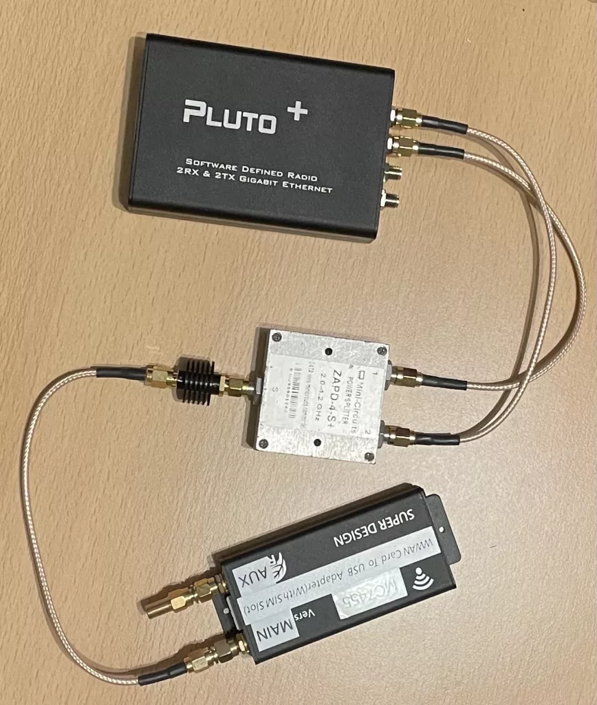
A power splitter and attenuator separate the TX and RX signals while protecting the SDR and UE from each other’s power amplifiers.
Make sure to connect to RF channel one, rather than two. Definitely not a mistake I made…..in my defence it was all upside down and backwards, covered in JTAG leads at the time 😅…..and the sun was in my eyes.
Building srsRAN and Supporting Libraries
I’ve described how to build srsRAN before, when experimenting with the LimeSDR. For for a more detailed version of the following see Private LTE with LimeSDR and srsRAN – Part 1 (Software).
In order to isolate the build, cmake is being provided with updated prefix and install prefix paths, such that it will install the required libraries and tools in a user specified location.
To allow this location to be customised, set an environment variable:
export SRSRAN_INSTALL=${HOME}/srsRAN
SoapySDR
To build the SoapySDR library itself:
sudo apt-get install cmake g++ libpython3-dev python3-numpy swig
git clone --branch soapy-sdr-0.8.1 https://github.com/pothosware/SoapySDR.git
cd SoapySDR
mkdir build && cd build
cmake -DCMAKE_PREFIX_PATH=${SRSRAN_INSTALL} -DCMAKE_INSTALL_PREFIX=${SRSRAN_INSTALL} ..
make -j`nproc` && make install
SoapySDR Pluto Plugin
To build the updated SoapySDR plugin for the Pluto+ which supports the low latency daemons and timestamping.
First we need LibIIO and LibAD3961. Ideally I’d have installed these from my distribution’s package manager. However Ubuntu 20.04’s repositories doesn’t contain the required 0.24 release of IIO. Therefore I opted to build these from source.
To build LibIIO:
sudo apt-get install libxml2 libxml2-dev bison flex libcdk5-dev cmake
sudo apt-get install libusb-1.0-0-dev libaio-dev
git clone --branch v0.24 https://github.com/analogdevicesinc/libiio.git
cd libiio
mkdir build && cd build
cmake -DCMAKE_PREFIX_PATH=${SRSRAN_INSTALL} -DCMAKE_INSTALL_PREFIX=${SRSRAN_INSTALL} -DUDEV_RULES_INSTALL_DIR=${SRSRAN_INSTALL}/etc/udev/rules.d -DHAVE_DNS_SD=OFF ..
make -j`nproc` && make install
To build LibAD3961-IIO:
git clone --branch v0.3 https://github.com/analogdevicesinc/libad9361-iio.git
cd libad9361-iio
mkdir build && cd build
cmake -DCMAKE_PREFIX_PATH=${SRSRAN_INSTALL} -DCMAKE_INSTALL_PREFIX=${SRSRAN_INSTALL} ..
make -j`nproc` && make install
To build the ADALM-PLUTO SoapySDR plugin:
git clone --branch sdr_gadget_timestamping https://github.com/pgreenland/SoapyPlutoSDR.git
cd SoapyPlutoSDR
mkdir build && cd build
cmake -DCMAKE_PREFIX_PATH=${SRSRAN_INSTALL} -DCMAKE_INSTALL_PREFIX=${SRSRAN_INSTALL} ..
make -j`nproc` && make install
Having installed everything to an unprivileged directory. There is one file which needs to be installed as root. The udev rules allowing the device to be accessed over USB without root privileges. This step can technically be skipped with the Pluto+ if its only ever going to be used via Ethernet. If being used via USB the rule can be added via:
echo 'SUBSYSTEM=="usb", ATTR{idVendor}=="0456", ATTR{idProduct}=="b673", MODE="666"' | sudo tee /etc/udev/rules.d/90-libiio_pluto.rules
sudo udevadm control --reload-rules && sudo udevadm trigger
srsRAN
To build srsRAN:
sudo apt-get install build-essential cmake libfftw3-dev libmbedtls-dev libboost-program-options-dev libconfig++-dev libsctp-dev
git clone --branch release_23_04 https://github.com/srsran/srsRAN_4G.git
cd srsRAN_4G
mkdir build && cd build
cmake -DCMAKE_PREFIX_PATH=${SRSRAN_INSTALL} -DCMAKE_INSTALL_PREFIX=${SRSRAN_INSTALL} -DUSE_LTE_RATES=ON ..
make -j`nproc` && make install
./srsran_install_configs.sh user
srsRAN Configuration & Launch
The final command in the srsRAN build notes above will have installed a copy of the reference configuration files into your home directory at ~/.config/srsran.
Edit ~/.config/srsran/enb.conf:
In the [enb] section, update:
n_prbto 25.
In the [rf] section, update:
tx_gainto 89.rx_gainto 20.
Add the following to the end of the section:
device_name = soapy
device_args = driver=plutosdr,hostname=pluto,direct=1,timestamp_every=5760,loopback=0
time_adv_nsamples = 40
Here hostname=pluto specifies where to find the Pluto+ on the network. I’ve added pluto to my hosts file, but providing an IP or a full DNS name here will work equally as well.
Edit ~/.config/srsran/rr.conf:
In the cell_list modify the first entry, updating:
dl_earfcnto 1575- Note the above will cause the unit to transmit in band 3. If like me you have a low end spectrum analyser and want to take a look. A better choice may be 2525 which will select band 5, placing the downlink at 881Mhz.
If you’ve previously been using a n_prb=6 configuration, for example for the Analog ADALM-PLUTO:
Edit ~/.config/srsran/sib.conf:
In the sib2 section, updating:
prach_freq_offsetto 4.
Edit .config/srsran/user_db.csv, providing your SIM card details. For more information on this see Private LTE with LimeSDR and srsRAN – Part 3 (SIM Cards) and Private LTE with LimeSDR and srsRAN – Part 4 (Config & Launch).
To launch srsRAN, assuming it was built and installed as described above.
First start the EPC application:
sudo LD_LIBRARY_PATH=${SRSRAN_INSTALL}/lib sh -c "cd ${HOME}/.config/srsran; ${SRSRAN_INSTALL}/bin/srsepc epc.conf"
Then start the eNodeB application:
echo "performance" | sudo tee /sys/devices/system/cpu/cpu*/cpufreq/scaling_governor
sudo LD_LIBRARY_PATH=${SRSRAN_INSTALL}/lib sh -c "cd ${HOME}/.config/srsran; ${SRSRAN_INSTALL}/bin/srsenb enb.conf"
A good startup should look something like this:
Starting eNodeB...
Active RF plugins: libsrsran_rf_soapy.so libsrsran_rf_lms.so
Inactive RF plugins:
---  Software Radio Systems LTE eNodeB  ---

Reading configuration file enb_pluto.conf...

Built in Release mode using commit 30d251687 on branch release_23_04_lms.

Opening 1 channels in RF device=soapy with args=driver=plutosdr,hostname=pluto,direct=1,timestamp_every=5760,loopback=0
Supported RF device list: soapy limesdr file
[WARNING] Unable to scan ip: -19

Soapy has found device #0: device=PlutoSDR, driver=plutosdr, hostname=pluto, label=PlutoSDR #0 pluto,
Selecting Soapy device: 0
[INFO] Opening label PlutoSDR #0 pluto...
[INFO] Opening hostname pluto...
Setting up Rx stream with 1 channel(s)
[INFO] Using format CF32.
[INFO] IP direct mode enabled!
[INFO] RX timestamping enabled, every 5760 samples
[INFO] Has direct RX copy: 1
Setting up Tx stream with 1 channel(s)
[INFO] Using format CF32.
[INFO] TX timestamping enabled, every 5760 samples
[INFO] Has direct TX copy: 1
Available device sensors:
 - xadc_temp0
 - xadc_voltage0
 - xadc_voltage1
 - xadc_voltage2
 - xadc_voltage3
 - xadc_voltage4
 - xadc_voltage5
 - xadc_voltage6
 - xadc_voltage7
 - xadc_voltage8
 - adm1177_current0
 - adm1177_voltage0
 - ad9361-phy_temp0
 - ad9361-phy_voltage2
Available sensors for Rx channel 0:
State of gain elements for Rx channel 0 (AGC supported):
 - PGA: 71.00 dB
State of gain elements for Tx channel 0 (AGC not supported):
 - PGA: 79.00 dB
Rx antenna set to A_BALANCED
Tx antenna set to A

==== eNodeB started ===
Type <t> to view trace
Setting manual TX/RX offset to 40 samples
Setting frequency: DL=1842.5 Mhz, UL=1747.5 MHz for cc_idx=0 nof_prb=25
RACH:  tti=8791, cc=0, pci=1, preamble=15, offset=7, temp_crnti=0x46
If all goes well your user equipment should now be able to find and register on the network.
Note the that the configuration above provides the maximum performance I’ve managed to achieve so far on the Pluto+, utilising 25 LTE physical resource blocks. Other options include, 15 and 6 PRBs.
For a 15 PRB configuration:
Edit ~/.config/srsran/enb.conf:
- Update
n_prbto 15. - Update
timestamp_everyproperty indevice_argsto 3840.
For a 6 PRB configuration:
Edit ~/.config/srsran/enb.conf:
- Update
n_prbto 6. - Update
timestamp_everyproperty indevice_argsto 1920.
Edit ~/.config/srsran/sib.conf:
In the sib2 section, updating:
prach_freq_offsetto 0.
Testing
iperf3
As with the ADALM-PLTUO, for initial testing, the goto tool was iperf.
On the machine running srsRAN (hosting the mobile network):
iperf3 -s
On the machine with the user equipment (in this case a Sierra Wireless MC7455):
iperf3 -c 172.16.0.1 -t 10 -R
Which resulted in the following encouraging trace:
Connecting to host 172.16.0.1, port 5201
Reverse mode, remote host 172.16.0.1 is sending
[  5] local 172.16.0.2 port 46868 connected to 172.16.0.1 port 5201
[ ID] Interval           Transfer     Bitrate
[  5]   0.00-1.00   sec  1.96 MBytes  16.4 Mbits/sec
[  5]   1.00-2.00   sec  2.07 MBytes  17.3 Mbits/sec
[  5]   2.00-3.00   sec  2.07 MBytes  17.4 Mbits/sec
[  5]   3.00-4.00   sec  2.07 MBytes  17.4 Mbits/sec
[  5]   4.00-5.00   sec  2.07 MBytes  17.4 Mbits/sec
[  5]   5.00-6.00   sec  2.07 MBytes  17.4 Mbits/sec
[  5]   6.00-7.00   sec  2.07 MBytes  17.4 Mbits/sec
[  5]   7.00-8.00   sec  2.07 MBytes  17.4 Mbits/sec
[  5]   8.00-9.00   sec  2.07 MBytes  17.4 Mbits/sec
[  5]   9.00-10.00  sec  2.06 MBytes  17.3 Mbits/sec
- - - - - - - - - - - - - - - - - - - - - - - - -
[ ID] Interval           Transfer     Bitrate         Retr
[  5]   0.00-10.03  sec  22.7 MBytes  19.0 Mbits/sec   15             sender
[  5]   0.00-10.00  sec  20.6 MBytes  17.3 Mbits/sec                  receiver

iperf Done.
Not too shabby at ~17.5Mbit/s.
Testing the upload by dropping the -R option:
Connecting to host 172.16.0.1, port 5201
[  5] local 172.16.0.2 port 48018 connected to 172.16.0.1 port 5201
[ ID] Interval           Transfer     Bitrate         Retr  Cwnd
[  5]   0.00-1.00   sec  1.52 MBytes  12.8 Mbits/sec    0    109 KBytes
[  5]   1.00-2.00   sec  1.43 MBytes  12.0 Mbits/sec    0    165 KBytes
[  5]   2.00-3.00   sec  1.18 MBytes  9.90 Mbits/sec    0    222 KBytes
[  5]   3.00-4.00   sec  1.55 MBytes  13.0 Mbits/sec    0    280 KBytes
[  5]   4.00-5.00   sec  1.24 MBytes  10.4 Mbits/sec    0    337 KBytes
[  5]   5.00-6.00   sec  1.43 MBytes  12.0 Mbits/sec    0    393 KBytes
[  5]   6.00-7.00   sec  1.68 MBytes  14.1 Mbits/sec    0    451 KBytes
[  5]   7.00-8.00   sec   954 KBytes  7.82 Mbits/sec    0    508 KBytes
[  5]   8.00-9.00   sec  1.06 MBytes  8.86 Mbits/sec    0    566 KBytes
[  5]   9.00-10.00  sec  2.36 MBytes  19.8 Mbits/sec    0    622 KBytes
- - - - - - - - - - - - - - - - - - - - - - - - -
[ ID] Interval           Transfer     Bitrate         Retr
[  5]   0.00-10.00  sec  14.4 MBytes  12.1 Mbits/sec    0             sender
[  5]   0.00-10.56  sec  11.7 MBytes  9.30 Mbits/sec                  receiver

iperf Done.
Again not bad at ~9Mbit/s.
Conclusion
If you’ve read this far, well done. It seems that as expected the Pluto+ manages to out perform the original Pluto, although not by quite as much as I’d hoped. It’s undoubtedly more convenient to connect over Ethernet, without additional supporting timing hardware but at the same time I was hoping for more speed.
In the current 25 PRB configuration the Pluto+ is managing to handle transmit and receive at a very respectable 16,000 UDP packets per second, or 22MBs in either direction. That doesn’t feel terrible for a pair of Cortex-A9’s running at 666Mhz. I tried the step to 50PRB, resulting in 32,000 packets in either direction but no dice, it can’t keep up. It gives it a good go though, reaching around 30,000 per second on the receive path. I’ve included htop and bmon in the firmware image if you want to take a look for yourself.
I was hoping to reduce the load by switching from standard 1500 byte Ethernet frames to 9000 byte jumbo frames. Only to find that the Cadence GEM Ethernet controller included in the Zynq doesn’t support them. Then considered instantiating an Ethernet controller in the FPGA fabric, which would support Jumbo frames. Although Xilinx’s licensing confused me somewhat at this point….I didn’t, and don’t think their synthesisable Ethernet controller is available in the community edition of their toolchain. I reserve the right to be wrong….but at the same time don’t think I am. Regardless the Ethernet physical interface is connected via the Zynq’s multiplexed input/output (MIO) interface, which goes directly to the hardware peripherals. Rather than the extended multiplexed input/output interface (EMIO) which is accessible from the FPGA side of the device, so it wouldn’t be possible anyway. Wish I’d checked that before looking up the licensing 🙈.
When developing the USB version for the Analog ADALM-PLUTO a reader suggested that I switch from 16-bit to 8-bit IQ samples. Given that the ADC/DAC in the Pluto/Pluto+ is 12-bits, we’re only going to be loosing 4 bits of resolution by doing this. Effectively halving the sample size, allowing the sample rate to be doubled, with 50PRB on the horizon. Although this would require some more hacking inside the FPGA, which as we know is were madness lies….although it’s secretly quite good fun.
Development Notes
The following usually end up stuffed in a readme somewhere. Given the number of repositories involved in this project I couldn’t decide which one to stash them in, so here they are…
Converting an FPGA bit file into a bin file, suitable for loading with the FPGA manager driver within Linux:
echo "all: { system_top.bit }" > bitstream.bif
bootgen -image bitstream.bif -arch zynq -process_bitstream bin -w on
Loading the new firmware on the Pluto+ while running, note that this doesn’t currently quite work….which is super annoying. It appears that even when all the drivers are unbound and rebound some sort of pointer mishap occurs within one of them and all the springs come out:
scp /media/user/Data1/plutosdr-fw/hdl/projects/pluto/pluto.runs/impl_1/system_top.bit pluto:/lib/firmware

echo 79024000.cf-ad9361-dds-core-lpc > /sys/bus/platform/drivers/cf_axi_dds/unbind
echo 79020000.cf-ad9361-lpc > /sys/bus/platform/drivers/cf_axi_adc/unbind
echo 7c400000.dma > /sys/bus/platform/drivers/dma-axi-dmac/unbind
echo 7c420000.dma > /sys/bus/platform/drivers/dma-axi-dmac/unbind

echo 41600000.i2c > /sys/bus/platform/drivers/xiic-i2c/unbind

cd /lib/firmware; echo system_top.bit.bin > /sys/class/fpga_manager/fpga0/firmware

echo 41600000.i2c > /sys/bus/platform/drivers/xiic-i2c/bind

echo 7c420000.dma > /sys/bus/platform/drivers/dma-axi-dmac/bind
echo 7c400000.dma > /sys/bus/platform/drivers/dma-axi-dmac/bind
echo 79024000.cf-ad9361-dds-core-lpc > /sys/bus/platform/drivers/cf_axi_dds/bind
echo 79020000.cf-ad9361-lpc > /sys/bus/platform/drivers/cf_axi_adc/bind
Debugging the FPGA design with Xilinx’s Integrated Logic Analyser (ILA) core. To enable debugging, within Vivado:
- Expand synthesised design, hit “Add debug”, follow wizard.
- Complete implementation and generate bitfile.
- Export hardware (system_top.xsa) and copy to pluto build directory.
- Re-generate pluto.dfu file.
- Load .dfu file to RAM using dfu-utils.
- Back in Vivado, open hardware manager, followed by open target to connect via JTAG and find debug core.
- Ensure JTAG frequency is lower than debug probe clock domain frequency. Selecting Properties -> PARAM -> FREQUENCY, having selected JTAG adapter, under localhost
Read samples from ADC and dump to terminal. Using groups of 8 bytes, timestamp should be visible at the start of each buffer, depending on the configuration.
iio_readdev -u local: -b 3844 -s 7688 cf-ad9361-lpc voltage0 voltage1 | hexdump -e '"%08.8_ax "' -e '8/1 "%02x""\n"'
Select which channel is used for RF loopback mode:
iio_reg -u 'local:' ad9361-phy 0x800003F5 0x20
	set to 0x00 normally for a loopback test on channel 1 (which will become 0x01 when loopback enabled)
	set to 0x20 for loopback test on channel 2 (which will become 0x21 when loopback enabled)
Overclocking, just a bad idea for now….I briefly tried it but didn’t attempt to load the produced image. Basic idea, tell Vivado a small lie, changing the speed grade of the part used from -1 to -2. This allows the PS’s PLL configuration, specifically the CPU clock to be increased above the usual 666Mhz limit. Whether the FPGA will accept a design for a higher speed grade part, currently unknown….if it does whether it’ll run it, also currently unknown. Whether voltages and temperatures are within limits also unknown.
Leave a Reply