Introduction
For some time now I’ve used a couple of Ruiden Riden RD6006‘s as general purpose power supplies (PSUs). Both of these units are equipped with their optional Wi-Fi module.
Following recent testing and development with a customer’s unit I found that I’d substantially worn the power button on one unit more than the other. Seems I have a go-to unit that does most of the work.
I’d also identified that it would be useful to be able to control the PSUs when running automated tests that require units to be power cycled.
The manufacturer provides a few options for this. A mobile app, which works but is clunky and doesn’t solve my automation issues. Along with a (Windows only) desktop app, which again works but doesn’t provide any external interfaces. At least as far as I could see, making automation difficult.
The mobile app (on iOS at least) only supports connecting via Wi-Fi, which can be a pain to configure and re-configure if the IP address of the mobile device ever changes.
The desktop app appears to prefer a USB connection, which is made on the front of the PSU leading to a trailing and easy catch cable. Recent versions appear to include Wi-Fi as an option but I’ve not tried this.
As an “evening” project….with a how hard can it be vibe I was hoping to replace the mobile app / desktop app with my own application. Allowing both PSUs to be controlled via a MQTT (message queueing telemetry transport) broker, using their built-in Wi-Fi modules.
I found at least a few projects on the web which have done something similar. Although they typically replace the firmware on the Wi-Fi module. I initially considered this, but wanted to see how far I could get without modifying the PSUs. Therefore everything that follows uses stock firmware on both the PSU and the optional Wi-Fi module.
This post walks through how I achieved this and what I learnt along the way. If you just want to try the software developed, jump to the Bridge, Provisioning and GUI use sections below.
Bridge
Implementation
Regardless of the connection method the Riden family of PSUs external interface makes use of the Modbus protocol.
Originally developed for programmable logic controllers (PLCs) used in industrial automation, Modbus provides amongst other functions the ability to read and write 16-bit virtual registers within the device. These registers allow for things like the set voltage and current as well as the output state, to be observed and modified.
Thanks to the hard work of others the register map for Riden family has been well documented, for example as part of Baldanos’s RD6006 python module providing USB control of the PSU.
When used over the USB connection, which is effectively a UART connection the Modbus RTU (remote terminal unit) binary protocol is used. So far so good, all perfectly normal, nothing to see here.
When connected via Wi-Fi, you might expect the TCP version of Modbus, Modbus TCP to be used. This version is specifically tailored to network connections. A typical arrangement would involve a Modbus server in the device listening for connections on TCP port 502. Accepting clients and servicing their requests. This all ends up a bit upside down and backwards when it comes to the Riden units.
The optional Wi-Fi module is neat but also a little limited. In Riden’s implementation, along with network credentials, it’s provided with an IP address to connect to. When used with the mobile apps this IP will be that of the mobile device on the Wi-Fi network. The Wi-Fi module opens a TCP connection to port 8080 on the configured server. Once open it bi-directionally bridges the TCP connection it’s created with its hardware UART connected to the PSU.
The software then continues to use the Modbus RTU framing as if it was connected via an asynchronous serial connection. Which is sort of is…..considering the final step of the transparent bridge.
This posed the first problem. While there are at least a few Python libraries out there that implement the Modbus protocol none of them can support this slightly odd arrangement out of the box.
The minimalmodbus library used by Baldanos above supports the RTU framing, but only over physical serial ports.
Another library pymodbus comes a lot closer. It supports the full gamut of Modbus connection types, from serial, through to RS485 and TCP/UDP. It even allows the RTU framing to be selected for use of a TCP connection, which is neat.
It doesn’t however support the reversed client/server role used here, where the client accepts a TCP connection from the server. Thankfully the library was structured such that a little subclassing and overriding would allow it to listen for and accept inbound connections from devices. Before treating them as client connection, like it had initiated them itself.
With the main Modbus shaped hurdle out of the way the remainder of the application involves connecting to an MQTT broker and marshalling messages back and forth between the PSU and network clients.
For this I selected the aiomqtt library, a Python asyncio wrapper around the popular paho-mqtt client library. Combined with pymodbus’s asyncio capabilities, the combination allows for Python asynchronous IO to be used throughout the application. This in turn allowing for multiple PSUs to be managed without the need for threads and their associated synchronisation / mutual exclusion issues. Or the management of IO multiplexing directly, with it neatly hidden behind an asyncio facade.
The final python application connects to a nominated MQTT broker while listening for incoming PSU connections on TCP port 8080. Upon connection a power supply’s details are queried (its model number and serial number), forming its identity. The connection is then added to the application’s list of available PSUs and the new PSU’s presence is advertised via MQTT.
MQTT clients may then place requests to read / write parameters from the PSU by publishing requests on topics based on the PSU’s identity. The application handles all of the Modbus communication and register packing / unpacking. Accepting requests and providing responses as JSON using scientific units.
The application may be requested to automatically query connected PSUs, publishing the current status periodically without having received a query request via MQTT.
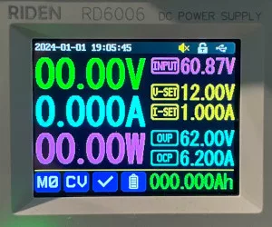
An example JSON message, containing the current PSU state will look something like the following:
{
  "connected": true,
  "period": 0,
  "model": 60062,
  "serial_no": 23024,
  "firmware_version": "1.41",
  "temp_c": 29,
  "temp_f": 84,
  "current_range": 0,
  "output_voltage_set": 12,
  "output_current_set": 1,
  "ovp": 62,
  "ocp": 6.2,
  "output_voltage_disp": 0,
  "output_current_disp": 0,
  "output_power_disp": 0,
  "input_voltage": 61.06,
  "protection_status": "normal",
  "output_mode": "cv",
  "output_enable": false,
  "battery_mode": false,
  "battery_voltage": 0,
  "ext_temp_c": 31,
  "ext_temp_f": 87,
  "batt_ah": 0,
  "batt_wh": 0,
  "presets": [
    {
      "v": 12,
      "c": 1,
      "ovp": 62,
      "ocp": 6.2
    },
...
    {
      "v": 5,
      "c": 6.1,
      "ovp": 62,
      "ocp": 6.2
    }
  ]
}
See the bridge README in the project repository for a full description of the topics and message fields.
Use
The bridge application is best installed on a system with a static IP address. Raspberry Pi’s make good candidates as does my lightweight Docker host.
Other than that it requires either a Python installation or Docker runtime. Along with access to a MQTT broker instance to communicate with. For this I’ve currently been using a Mosquito instance, hosted in a separate Docker container.
The bridge README contains examples of different deployment options. For testing, launching the pre-built docker container is the simplest. It may be launched as follows:
docker run --rm -it -p 8080:8080 -v .:/app/config pgreenland/riden_psu_mqtt_bridge
On first run, the container will generate a config file config.ini in the current directory and quit.
Modify config.ini to specify your MQTT broker hostname and other connection options, username/password for example. Then launch the docker container again. If all goes well you should see:
[2024-01-01 18:13:53,199] [RD60xxToMQTT] [INFO] MQTT task running
[2024-01-01 18:13:53,203] [RD60xxToMQTT] [INFO] PSU task running
[2024-01-01 18:13:53,221] [RD60xxToMQTT] [INFO] MQTT connected!
If so, the service has connected to your MQTT broker and is waiting for PSUs to connect. Next we move onto provisioning a PSU to talk to it. If you’re not interested in how this process works, skip again to the use of the provisioning script.
Provisioning
Implementation
The optional Wi-Fi module supplied with the Ruiden Riden RD series of PSUs is based around Ai Thinker’s ESP-12F Wi-Fi module. Which in turn is based on Espressif’s ESP8266 Wi-Fi module.
Running a custom firmware developed by Ai Thinker allows the module to be controlled via AT commands as indicated by its datasheet. It provides a basic set of services, allowing it to connect to Wi-Fi networks and establish / bridge TCP connections to its UARTs. Amongst a few other options.
The PSU makes use of this AT command set to manage the module, configuring the Wi-Fi before establishing a transparent bridge to the host computer. Which will end up looking similar to a PSU connected directly via USB (in that the same Modbus RTU format used, just over a different transport).
The mobile app includes support for provisioning the PSU’s Wi-Fi connection, providing it with the network SSID and password.
Unlike most products which first operate as a Wi-Fi access point, serving a network which the user is required to join. Allowing them to provide provisioning information. The Ai Thinker module takes a different approach.
It’s provisioning feature is based around Espressif’s ESP-Touch protocol, which is supported by the ESP8266.
It works by implementing what could best be described as a side-channel attack. Deliberately leaking information from within an encrypted network by manipulating a property of the network. In this case to advertise the credentials of the network.
Before the PSU joins the Wi-Fi network it’s able to monitor 802.11 packets being transmitted between hosts and access points, but isn’t able to decrypt them. It can however monitor the lengths of the encrypted payloads carried by these packets.
The pairing process involves encoding the required information via the transmission of UDP packets of varying lengths within the encrypted network. Something that can easily be achieved from an application from user space. The data content of the packets transmitted is irrelevant (as the PSU can’t decrypt them) but a small amount of information can be encoded by modifying the length of each packet transmitted.
The packets seen by the PSU can be thought of as being length + overhead bytes long. Where the overhead is a fixed value added by the encryption scheme in use.
A training signal is therefore included, with a repeated sequence of lengths being sent. This allows the PSU to identify a candidate device to monitor, as well as work out the overhead added to the packets by the encryption. Based on its knowledge of the size of packets transmitted in the training signal.
A separate data stream is then sent as a series of broadcast (or multicast) UDP packets, from which the PSU is able to recover the encoded information.
The RuiDeng Riden uses the ESP-Touch provisioning process in a slightly odd way.
A single execution of the process allows for an SSID, password, BSSID and IP address (for the device to contact once connected) to be transferred.
The PSU makes use of two iterations. The first iteration it transmits the IP address of the mobile device in place of the network password. The second iteration it transmits the actual network password in the password field. Why they didn’t use the IP field, dedicated for this purpose I’ve no idea 🤷.
If using the official app it includes a checkbox which the user is asked to select when the PSU displays an IP address. The app switches from the first to second iteration of the algorithm when this input is provided.
However this means that it’s easy to advertise the IP address that the PSU should connect to which I’ll be making use of.
Espressif thankfully provide example iOS and Android applications demonstrating this process. The Android version was used as a reference to create my own version. Which being written in Python should be relatively portable.
A full README for the provisioning script can be found in the project repository.
Use
To provision a PSU to connect to the bridge application described above, a Python provisioning script provided in the project repository can be used.
A PC connected to the 2.4Ghz wireless network that the power supply is to join along with a Python installed is required.
The script can either be downloaded from the repository directly, or the repository can be cloned with git:
git clone https://github.com/pgreenland/RidenRD60xxMQTT.git
cd RidenRD60xxMQTT
cd provisioning
Before starting the script the PSU needs to be configured to communicate via Wi-Fi.
The notes and screenshots below were taken from my RD6006 running the latest firmware, version 1.41 at the time of writing.
- From the home screen enter the menu system by selecting
Shiftfollowed by0.
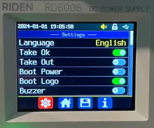
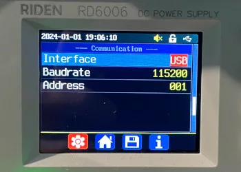
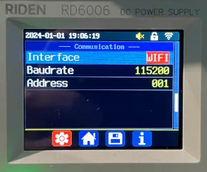
- Navigate through the menu with the
UpandDownarrow keys to find the communication section. Once found, ensure theInterfaceoption is set toWIFIusing the dial input. Once done click the dial button to confirm the selection and exit the menu.
- Now power cycle the unit, via the front panel button. Upon power up you should be presented with the following
WiFi Configscreen.
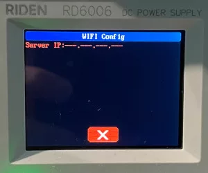
If the unit displays an IP address, for example you’ve connected it to a mobile device in the past. You should see a Reset button, select it with the Left and Right arrows and hit the Enter key to reset the config. For example:
- With the unit waiting at the
WiFi Configscreen we can start the provisioning script. ReplacingSSIDwith your 2.4Ghz network SSID,PASSWORDwith the corresponding network password andIPwith the IP address of the machine hosting the bridge application or Docker container.
python3 provision.py 'SSID' 'PASSWORD' IP
If your machine has multiple network adapters you will need to provide an additional argument --adapter_ip ETH_IP replacing ETH_IP with the IP address assigned to your Wi-Fi adapter. This allows the script to ensure the UDP packets generated leave via the Wi-Fi card, such that the PSU can capture them.
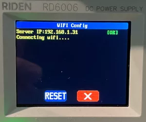
When started the script should output the following:
Please press enter when power supply displays message 'Connecting wifi'...
At this point it’s started transmitting the first phase of the provisioning process. Watch the PSU screen and hit enter in the script when the IP address field is filled in with the details you entered above. For example:
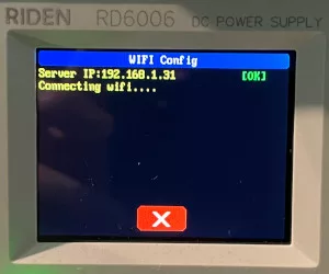
- At this point half the information has been transferred to the PSU. Press
Enterin the provisioning script, after which it will display the following:
Please press enter when power supply displays message 'Connecting wifi'...
Please press enter when power supply displays message 'Connecting server'...
Again watch the PSU screen and hit enter in the script when the message “Connecting server…” is displayed, for example:
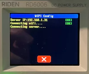
- At this point the provisioning script should have exited and the PSU will connect to the Wi-Fi and should go on to connect to the bridge application. The terminal output should look similar to the following:
[2024-01-01 19:53:37,292] [RD60xxToMQTT] [INFO] PSU connected (192.168.1.143:45713)
[2024-01-01 19:53:37,614] [RD60xxToMQTT] [INFO] PSU 192.168.1.143:45713's identity is 60062_23024, it's name is 'Unnamed'
If you’ve got this far, your PSU should now be manageable via MQTT. See the bridge README for information on the message and topic formats. Or alternatively use the GUI below to control and monitor it.
Note that the PSU provisioning process can take some time, in the order of 5 minutes sometimes. Given how it works it presumably helps to perform it with the Wi-Fi network largely idle, other than the device generating the provisioning packets.
GUI
Implementation
I was initially going to leave sort of useful interface to publish / subscribe to MQTT messages as “an exercise for the reader”.
While a command line version may be in the pipeline soon, I thought I’d start with a GUI attempting to mimic the display of the RD6006.
I’d discovered PySimpleGUI a while ago and was waiting to find an appropriate project to use it for. It’s designed to act as a simplified wrapper around a few different GUI frameworks, Python’s Tk in my case. As a first impression it went fairly well. Although I experienced lots of little bumps along the way. Thankfully most all of the questions I had were answered in their Github issues history.
As with the bridge I made use of the aiomqtt library. Running the MQTT communications using Python asyncio, in its own thread. The GUI is then able to run on the main thread, with messages being marshalled back and forth between it and the asyncio thread.
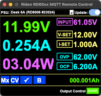
Here’s a sneak peak of the GUI displaying the current status of my RD6006 while supplying power to a load:
Use
The GUI application can be ran on any machine with access to the MQTT broker used by the bridge and a Python installation. See the GUI README for notes on how the different methods of launching the GUI.
For convenience I’ve published self-contained application images, which include a Python interpreter and the required libraries for Windows, macOS and Linux on GitHub, the first release can be found here.
Linux and macOS users should be fine with these packages however Windows users (of which I am not) may have issues. I had a bit of a battle in a Windows 10 VM creating the packaged GUI, with PyInstaller triggering the Windows Defender “anti-virus”. Thinking the self-extracting package which had just been created was a Trojan. I’m 99.999% sure it isn’t and suspect someone has done something naughty with PyInstaller generated packages in the past. Which may have lead to their signature to be included in the Windows Defender definitions.
If you’re using Windows, I both salute and feel for you. If defender gets all “defensive”, running from the raw source may be your best bet. If you can work out how to get your chosen version of Python installed and not what “the store” (all hail the store) wants you to install that is 🫠.
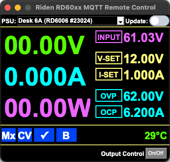
Upon first run the application will create and open a config file, similar to the bridge config file. Requesting the details required to connect to the MQTT server. Once configured close and re-open it and you should see any connected power supplies listed, something like this:
The “Update” toggle switch in the top right corner, controls whether the bridge service periodically (every 250ms by default) queries the power supply, updating the GUI. This isn’t toggled by default as whenever a command is sent to the PSU, it locks out the front panel buttons (as indicated by a closed padlock at the top of its screen) for a short period.
Regardless of “Update” toggle switch state, the “Output Control” button, along with “V-Set”, “I-Set”, “OVP”, “OCP” and “Mx” buttons can be used to configure parameters of the power supply. V/I set being the set voltage and current. OVP/OCP being the over-voltage/current limits and Mx allowing a different profile to be selected. With the fields on screen updating in response to the PSU confirming the setting having changed (if updates are enabled)
Typically I’ll enable updates when opening the GUI and only disable it if I need to interact with the PSU’s front keypad directly for whatever reason.
The “CV”, “✔️” and “B” lights are all functional, matching their equivalents on the PSU screen.
“CV” will change to “CC” and go red when the PSU enters constant current mode.
Likewise if either the over-voltage or over-current protection is tripped the “✔️” will change red and indicate which limit was breached.
The “B” stands for battery, unfortunately all the springs come out of Ubuntu 20.04’s Xlib library when attempting to display the cute little battery emoji I originally had in its place. When a battery is connected for charging this will turn red as the icon on the PSU screen does.
Limitations
There are a few annoying limitations which I’ve not yet managed to solve. These generally revolve around the PSU’s presets feature.
When the PSU powers up, it appears it always starts in preset M0, which is otherwise inaccessible on the front panel. It appears this is a special preset used just for power-up. When changing the V-Set or I-Set for them to be stored over power cycles the bridge modifies the values associated with preset M0. Likewise the OVP and OCP values displayed are from preset M0.
The currently selected preset number isn’t available via the Modbus interface. Hence why there’s an Mx where there would usually be the preset selection. In the PSU’s Modbus definitions there’s a register for changing the preset, but when read back it doesn’t contain the value of the currently selected preset 🙈.
Therefore the main limitation is that once a preset has been selected, the OVP and OCP values (read from M0, will no longer match what the PSU us actually using, or is displayed on it’s screen). Given there’s no way to read which preset is currently selected, there’s no way of knowing this is the case and the user can be inadvertently mislead by the GUI.
If however you only use preset M0 like me and had to read the user manual to look into the preset feature, everything will work fine 😅.
Conclusion
Evening project I thought, how hard could it be? I thought….Well it turned out to take a bit longer than an evening, and be a bit harder than I imagined. More like 5 non-working days over Christmas and New Years. However the next time I need to toggle the power on a unit, after the debugger looses control of its target for the 50th time today I can do it all without having to reach all the way over to the PSU and wear the power button out any further 😁.
The software developed for this project is available on GitHub.
Leave a Reply