Introduction
Recently I decided to purchase and restore a few Apple Macintosh SE/30 computers….because….umm…..reasons.
These machines were sold by Apple between January 1989 and October 1991. While ageing relatively well over the last 30 or so years, they have an Achilles’ heel, which has lead to the premature death of many of these adorable little machines.
This being the inclusion of a lithium battery to keep its realtime clock (RTC) going and data in its parameter random access memory (PRAM) safe while the machine is powered off.
Unlike the small coin cell battery you might find in a modern machine these batteries are monsters in comparison. If left unchecked they eventually fail and they spew their corrosive innards all over the inside of the machine.
The area hit first by the corrosive goo is typically the RTC circuitry, which is located next to the battery. Along with the system memory address decoding logic located on the opposite side.
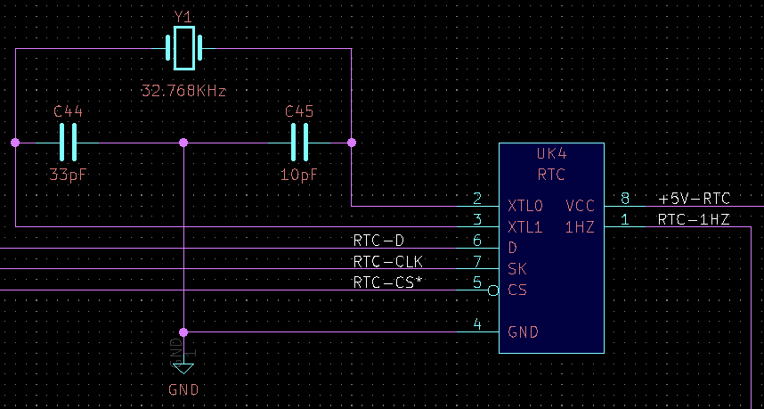
Here’s what the realtime clock and backup battery circuitry should look like:

The components of interest here being the custom Apple RTC chip itself, located directly below the battery. Diodes D1 and D2, which supply the RTC with power from either the system’s power supply or the battery. Along with a crystal Y1, a 32Khz watch crystal used as a time reference.
Here’s what the RTC circuitry was looking like in one of my machines:

One of the previous owners has cleaned up the battery acid relatively well, the board only has some minor damage. It seems the battery holder is rusted out. D1 (supplying power from the battery to the RTC) is gone, along with its solder pads. The crystal appears to have gone AWOL at some point and the legs of the RTC IC are showing some corrosion from their time exposed to the battery acid.
Having got the machine going again after repairing a few address lines (casualties of the battery) and replacing the missing crystal it seems the RTC is still alive and kicking. It maintains the system time over a reboot and the settings it’s responsible for (a variety of things from startup disk, to the mouse cursor speed).
While the system failing to maintaining its time over a power cycle isn’t a big deal, the loss of the settings, especially the startup disk selection is a pain.
Aside from jury rigging a battery up to the board though an appropriate diode, I wondered what other options might exist to maintain the settings without introducing a new source of future acid leaks.
Possible Solutions
It seems that other folks beat me to the idea of replacing the Apple RTC module with a small microcontroller containing non-volatile storage. For example the following Reddit post links to some code in PasteBin. With an improved version by another developer hosted on GitHub.
Both of these projects make use of a Microchip ATTiny85 microcontroller, which in the PDIP-8 package is virtually a pin-compatible a drop in replacement for the original Apple RTC chip.
As with everything silicon related at the moment it seems these chips are in short supply. Thankfully I was able to score a few on eBay…at only a 400% markup 😠.
Built and flashed the firmware, dropped it in the mac which now has a DIP socket for ease of tinkering…..no dice, the mac doesn’t seem to like its new RTC and refuses to boot.
To the logic analyser!
What’s Wrong?
Cross-referencing the source code of the emulator with an excellent open source KiCad schematic of the machine, generated from the original Apple engineering drawings it seems that the interface between the RTC and rest of the system consists of three lines.
Hooking the logic analyser up to the system with its original Apple RTC, we see transfers similar to the following.
The interface consists of a chip select line (CS), data line (D) and clock line (SK). The data line is bi-directional and as such is pulled up to VCC by a resistor, allowing it to be driven by either the host or device.
Apple’s book Inside Macintosh Volume III provides a description of the protocol used by the RTC, along with details of how to implement software on the Mac to communicate with it.
It appears that there are at least two generations of RTC chip used by Apple in these early machines. An early model which contained 20 bytes of PRAM and a later model (as used in the SE/30) which contained 256 bytes of PRAM.
Apple’s book provides a description of the protocol used to access the 20 byte model RTC, with the emulated RTC providing an example of how to access the 256 byte model.
Transfers always originate from the host device.
A transfer to / from a 20 byte device, which I’ll refer to as a “regular” transfer is performed as follows:
- Chip select line is asserted.
- 8-bit command / address byte is clocked out of the host.
- 8-bit data byte is clocked out by the host or device depending on the command / address byte. The clock line however is always driven by the host.
- Chip select line is de-asserted.
The command / address byte is structured as follows:

Bit 7 indicates whether the command is a read or write request (with 0 = write and 1 = read). Bits 6-2 form the address. Bits 1-0 should always read 10.
The Apple book provides details of how the address bits are decoded:
| Address | Contents | Address | Contents | |
|---|---|---|---|---|
| 0x00 | Seconds 0 (LSB) | 0x10 | PRAM High 0 | |
| 0x01 | Seconds 1 | 0x11 | PRAM High 1 | |
| 0x02 | Seconds 2 | 0x12 | PRAM High 2 | |
| 0x03 | Seconds 3 (MSB) | 0x13 | PRAM High 3 | |
| 0x04 | Seconds 0 (LSB) | 0x14 | PRAM High 4 | |
| 0x05 | Seconds 1 | 0x15 | PRAM High 5 | |
| 0x06 | Seconds 2 | 0x16 | PRAM High 6 | |
| 0x07 | Seconds 3 (MSB) | 0x17 | PRAM High 7 | |
| 0x08 | PRAM Low 0 | 0x18 | PRAM High 8 | |
| 0x09 | PRAM Low 1 | 0x19 | PRAM High 9 | |
| 0x0A | PRAM Low 2 | 0x1A | PRAM High 10 | |
| 0x0B | PRAM Low 3 | 0x1B | PRAM High 11 | |
| 0x0C | Test | 0x1C | PRAM High 12 | |
| 0x0D | Write-Protect | 0x1D | PRAM High 13 | |
| 0x0E | Extended Cmd | 0x1E | PRAM High 14 | |
| 0x0F | Extended Cmd | 0x1F | PRAM High 15 |
Addresses of note include 0x0-0x7, which contain a 32-bit seconds counter representing the time. Address 0x0-0x3 being mirrored in 0x4-0x7.
Address 0x0D being a write-only write protection register. Where bit 7 represents the write protection status. With 0 = write protected and 1 = writing allowed.
Address 0x0E and 0x0F are unimplemented in the 20 byte RTC. In the 256 byte model they indicate an “extended” command, used to access the remainder of the PRAM.
In order to access the full 256 bytes of PRAM in the later model of RTC an “extended” command was introduced. I wasn’t able to find any concrete documentation on this command but the emulated RTC code describes it well. An extended command consists of two command / address bytes, followed by a data byte.
The command / address byte pair is structured as follows:
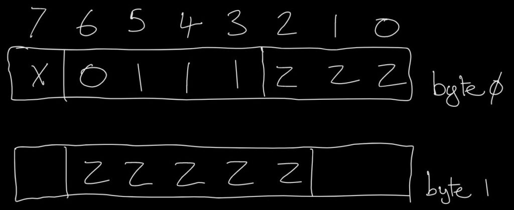
Here the 8-bit address required to address 256 bytes of PRAM is split in half. The three most significant bits are transmitted as the least significant bits of the first byte. The five least significant bits are transmitted as bits 6-2 of the second byte. The read/write bit is the same as with the regular command. The remaining bits are unused (although I’ve not confirmed what values they take).
The later released RTC modules implement both commands, with the 20 bytes of PRAM available from the earlier model available via both the regular command and extended command at the same addresses.
Armed with this info I was able to knock together a quick Arduino sketch, emulating the regular / extended reads and writes. Adding short delays where appropriate to get the timing as close as possible to that observed by in the logic analyser captures.
After a bit of debugging the Apple RTC is happily responding to commands, allowing the PRAM to be read and written. The ATTiny emulated RTC however is not.
Nosing around the codebase there was an interesting note regarding clocking. The ATTiny85 accepts a variety of different clock sources, including an external clock, an external high or low frequency crystal oscillator. As well as an internal RC oscillator and a dedicated watchdog oscillator.
The note reads as follows:
   * The serial data clock needs to be able to operate at a frequency
     of at least 1 kHz, maybe up to 20 kHz.
   * Because of the requirement on the serial clock speed, the AVR
     core clock speed should be around 8 MHz, given that it can take
     about 100 cycles to process one edge of the serial data clock.
Open-source software emulated RTC, hosted on GitHub
Ideally the microcontroller would be clocked from the external 32Khz clock, allowing for accurate timing. However this isn’t fast enough to allow the controller to process the incoming serial data stream. For that an 8Mhz system clock is suggested to handle the serial data arriving with a clock of upto 20Khz. The microcontroller is therefore using its internal RC oscillator, which operates at 8Mhz.
Wait a minute……the clock captured by the logic analyser was faster than that…..quite a bit faster actually, at 250Khz on average.
Increasing the delays in the Arduino sketch to slow the transfer down by a factor of 10 and boom, we’re in business. The emulated clock springs into life and starts responding with the time, as well as allowing PRAM byte to be read and written.
It seems the original software which was developed for a different Mac (Apple’s Mac Plus I believe) which may use a much slower serial clock than the SE/30, although I don’t have access to a machine to confirm this.
The Fix
Looking at the codebase, it appears to use the ATTiny’s pin change interrupts to detect events on the chip select and clock lines. Updating variables with the latest state. The main thread then uses these variables to advance a state machine, receiving the command, before accepting data from or returning data to the host, sampling or driving the data line at the appropriate time.
My first thought was, can we move everything inside the interrupt handler, ditching the state machine and overhead associated with it. While the cardinal rule of interrupt handlers is make them short, the RTC only has three jobs to do. Keep time, store its PRAM contents and reply to the host.
Here’s what I came up with:
ISR(PCINT0_vect)
{
	/* Bit counter - count down with while loops allowing gcc to perform one less comparison */
	uint8_t uiBit;

	/* Serial address (base and extended) */
	uint8_t uiAddrBase = 0;

	/* Rising edge on enable (chip deselected), stop early */
	if (mIsEnableHigh())
	{
		timingPinHigh();
		return;
	}

	/* Falling edge on enable (chip selected), receive address bits */
	uiBit = 8;
	while (0 != uiBit)
	{
		/* Sample bit on rising edge, while monitoring enable (except after last bit) */
		while (!mIsClockHigh()) if (mIsEnableHigh()) return;
		timingPinLow();
		uiAddrBase = (uiAddrBase << 1) | mIsDataHigh();
		uiBit--;
		timingPinHigh();
		if (0 != uiBit) while (mIsClockHigh()) if (mIsEnableHigh()) return;
	}

	/* Store address in global variable to save the code being optimised away */
	uiDummyAddr = uiAddrBase;
}
Hijacking a spare pin to act as a timing output, I captured the following:

So it works but only just. With the ATTiny operating at 8Mhz we come within 120ns of missing the first bit period.
Nosing at the generated assembly listing, with optimisations enabled the compiler hasn’t done anything crazy. My assembly foo on the AVR isn’t strong enough to beat it I fear.
Next option, more speed. The ATTiny85 is one of the few (possibly only) members of the family to include a phase locked loop (PLL) clock option, allowing us to step the system clock up from 8Mhz to 16Mhz.

That’s more like it, sampling just before the middle of each bit.
Transmission wise, we can do the same thing. For testing generating a slightly contrived example that doesn’t handle any address decoding. Simply accepting a read request and responding with a fixed value:
ISR(PCINT0_vect)
{
	/* Bit counter - count down with while loops allowing gcc to perform one less comparison */
	uint8_t uiBit;

	/* Serial address (base and extended) */
	uint8_t uiAddrBase = 0;

	/* Serial data */
	uint8_t uiData = 0xA5;

	/* Rising edge on enable (chip deselected), stop early */
	if (mIsEnableHigh())
	{
		timingPinHigh();
		return;
	}

	/* Falling edge on enable (chip selected), receive address bits */
	uiBit = 8;
	while (0 != uiBit)
	{
		/* Sample bit on rising edge, while monitoring enable (except after last bit) */
		while (!mIsClockHigh()) if (mIsEnableHigh()) return;
		timingPinLow();
		uiAddrBase = (uiAddrBase << 1) | mIsDataHigh();
		uiBit--;
		timingPinHigh();
		if (0 != uiBit) while (mIsClockHigh()) if (mIsEnableHigh()) return;
	}

	/* Store address in global variable to save the code being optimised away */
	uiDummyAddr = uiAddrBase;

	/* Send data */
	uiBit = 8;
	while (0 != uiBit)
	{
		/* Change data when clock low, before waiting for rising edge, while monitoring enable */
		while (mIsClockHigh()) if (mIsEnableHigh()) goto AbortSend;
		timingPinLow();
		if (uiData & 0x80)
		{
			/* Switch pin to input mode, allowing it to be pulled up externally */
			mSetDataPinHigh();
		}
		else
		{
			/* Switch pin to output mode, pulling it low */
			mSetDataPinLow();
		}
		uiData <<= 1;
		uiBit--;
		timingPinHigh();
		if (0 != uiBit) while (!mIsClockHigh()) if (mIsEnableHigh()) return;
	}

	/* Give host a chance to sample last bit, wait for enable to go high */
	while (!mIsEnableHigh());

	AbortSend:
		/* Switch pin to input mode, allowing data line to float after completion / abort */
		mSetDataPinHigh();
}
Timing it as before:

Well it works, sort of. The Arduino correctly receives the transmitted value most of the time, with only the occasional bit error. It seems the timings are a bit too tight. With often around 40ns to 60ns before the rising edge. In the example above -10ns. The data line registered as high after the rising clock edge 😬.
How about replacing the transmission routine in C with some hand crafted assembly? I can do better than a compiler right?
/* Send data */
asm volatile(
	/* Init bit counter */
	"ldi %[cnt], 0x08\n\t"

	/* Enter loop */
	"serial_write_loop_%=:\n\t"
		/* Wait for clock to be low, while monitoring enable */
		"serial_write_clk_low_%=:\n\t"
			"sbic %[pinb], %[en_pin]\n\t"
			"rjmp serial_write_done_%=\n\t"
			"sbic %[pinb], %[clk_pin]\n\t"
			"rjmp serial_write_clk_low_%=\n\t"

		/* Set test pin low (output) */
		"sbi %[ddrb], %[test_pin]\n\t"

		/* Shift data bit out of data register */
		"cbi %[ddrb], %[data_pin]\n\t"
		"sbrs %[out], 7\n\t"
		"sbi %[ddrb], %[data_pin]\n\t"
		"lsl %[out]\n\t"

		/* Set test pin high (input) */
		"cbi %[ddrb], %[test_pin]\n\t"

		/* Decrement bit counter and exit loop if zero */
		"dec %[cnt]\n\t"
		"breq serial_write_done_%=\n\t"

		/* Wait for clock to be high */
		"serial_write_clk_high_%=:\n\t"
			"sbis %[pinb], %[clk_pin]\n\t"
			"rjmp serial_write_clk_high_%=\n\t"

	/* Continue serial write loop */
	"rjmp serial_write_loop_%=\n\t"

	/* Completed serial tx */
	"serial_write_done_%=:\n\t"
	:
		/* Outputs */
		[cnt] "+r" (uiBit),
		[out] "+r" (uiData)
	:
		/* Inputs */
		[pinb] "I" (_SFR_IO_ADDR(PINB)),
		[ddrb] "I" (_SFR_IO_ADDR(DDRB)),
		[en_pin] "I" (uiPinEnable),
		[clk_pin] "I" (uiPinClock),
		[data_pin] "I" (uiPinData),
		[test_pin] "I" (uiPinXtal2)
	:
		/* Clobbers - none */
);

/* Give host a chance to sample last bit, wait for enable to go high */
while (!mIsEnableHigh());

/* Switch pin to input mode, allowing data line to float after completion / abort */
mSetDataPinHigh();
Timing as before:

A marginal improvement, rising clock edges are still missed occasionally. Considering the additional complexity of inline assembly it probably isn’t worth it.
Having extended the code to decode the addresses, load / store data and increment the clock, does it work on the mac?
Yes it does, settings and date appear to be stored correctly and it passes the hardware tests in one of the available test tools.
Looking a little further into the host side implementation it would seem the main processor in the mac is communicating with the RTC through one of its versatile interface adapters. Essentially implementing the same bit-bashed serial my Arduino sketch is performing. Therefore it makes sense that I’m getting away with being a tiny bit liberal on my data bit changes vs clock edges.
I attempted to add a timeout mechanism to the serial interrupt, allowing the code to be used as an RTC replacement for a mac with a battery. Without such a mechanism the code will get stuck in the interrupt handler. Having detected the enable line falling as the host is powered down it will begin waiting indefinitely for the rising edge of the clock. Causing it to spin in the interrupt, while at the same time not incrementing its clock. Unfortunately the code added for this pushed the timings out just that little bit too much and caused the first address / command bit to often be missed. An extension for another day maybe.
For now though my problem is solved, I’ve now got an RTC which remembers the system’s settings without power.
The code developed for this project is available on GitHub.
Update: 29th Dec 2022
I ran my timeout problem past a colleague who suggested I might consider using the integrated watchdog timer. While I suspect he meant for me to use it in its traditional sense. Allowing the system to detect and correct the stall within the interrupt handler. It got me looking at it as another potential timer.
The watchdog module in the ATTiny85 operates much like any other watchdog module. It’s driven by its own independent oscillator. Featuring a configurable divider, controlling its period. It provides a convenient means of reseting it, via a dedicated instruction. While of course providing the looming threat of a system reset if it isn’t properly cared for.
Additionally it may be configured to generate interrupts. If the watchdog is enabled an interrupt may be used as a heads up that something’s wrong, allowing a corrective action to be taken instead of rebooting the system immediately. It appears that the watchdog and its interrupts can be used independently. That’s to say that the watchdog timer will be running if either the watchdog is enabled, or its interrupt is enabled. Therefore I can use the watchdog as a simple timeout mechanism without having to fully enable it and therefore service it to avoid restarts.
The default configuration of the watchdog on the ATTiny85 provides a rough timeout of 16ms which is a tiny bit too long (we may miss some of the 8ms timer ticks) but it’ll get the job done.
This functionality may be enabled with just a few instructions:
wdt_reset();
WDTCR = _BV(WDIE) | _BV(WDIF);
And disabled with a similar few:
wdt_reset();
WDTCR = _BV(WDIF);
The serial transmit and receive code can then monitor the watchdog’s interrupt flag for a timeout while going about its normal business:
if (WDTCR & _BV(WDIF))
{
    /* Timed out....poor show */
}
Unfortunately I haven’t got a mac with intact battery circuitry, however I was able to easily simulate the condition with the help of an Arduino sketch, with the RTC seemingly happy to abort a transfer at the start or mid way through.
Additionally for the “real” RTC experience I’ve added a compilation option, allowing the EEPROM backup of the time and PRAM contents to be disabled for battery powered operation.
Update: 19th Nov 2024
Following a recent question in the comments, it’s worth nothing that the ATTiny RTC emulator described here can be dropped straight in, in place of Apple’s original RTC chip.
No modifications are required to the logic board. In fact, the battery, diode D1, supplying power to the RTC from the battery and the original crystal Y1 can all be absent.
One slight wrinkle to be aware of. I developed the software for the RTC emulator based on the excellent work of others, making use of the ATTiny85 for it’s drop-in ability. For my battery-less machines, saving the settings and boot options was the most important thing for me. There was some thought put into keeping the RTC running on battery while the machine is off, although this hasn’t been heavily tested. Given the power consumption of the ATTiny85 I don’t suspect it will last a particularly long time when running from an RTC battery.
Leave a Reply