Introduction
Previously I got the open source LTE stack srsRAN working with the low cost LimeSDR. Since then I’ve been considering even lower cost and more readily available options. While the LimeSDR is great value for money considering its performance, it’s overkill for testing the IoT devices I’ve been working on recently.
Having bumped into the Analog ADALM-PLUTO some time a go I wondered if it could be used for LTE simulation. Initially the answer was no, as there was no support for the transmit and receive timestamping required by LTE.
The srsRAN team implemented the missing timestamping functionality recently, targeting boards which use similar architectures, consisting of a Xilinx Zynq paired with an Analog RF Transceiver. They even produced a build of their updated hardware descriptor language code (HDL) specifically for the ADALM-PLUTO, which can be loaded on top of the stock Analog firmware.
Having initially given the released build a go I was hopeful however found that not all was well. It seemed that the ADALM-PLUTO simply wasn’t able to keep up or stay in sync with the PC. While the network would occasionally appear to be visible to the mobile device any attempts to register with it would be met with a barrage of errors from the eNodeB application.
This post covers implementing my own timestamping solution, specifically for the ADALM-PLUTO. Using a dash of inspiration from srsRAN’s implementation, I produce my own version of the HDL code. I take a slightly lighter touch approach than the SRS team, adding a pair of hardware blocks to implement the functionality. I then implement a new system service to communicate with the host PC running srsRAN. Finally updating the host PC’s ADALM-PLUTO module, part of the SoapySDR driver, exposing the new timestamp support to applications.
With all the various components in line, it then becomes a simple case of configuring srsRAN to use the ADALM-PLUTO as its RF interface and throwing the switch.
This article got a bit long. If you’re just interested in trying and don’t care too much about the long and arduous journey or ADALM-PLUTO’s internals, skip ahead to Booting / Upgrade.
Analog ADALM-PLUTO Architecture
The Analog ADALM-PLUTO is part of Analog’s active learning module family of low cost development boards aimed at those wishing to learn and experiment with software defined radios (SDRs). As such Analog provide a vast amount of high quality documentation on every aspect of the platform, accessible through their Wiki.
The ADALM-PLUTO features the following architecture:
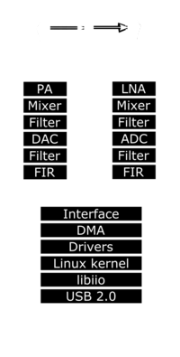
The two main components are the Analog AD9363 RF Transceiver and Xilinx Zynq 7000 Series System on Chip (SoC).
The AD9363 contains the necessary amplifiers and filters, along with digital to analog and analog to digital converters. Allowing it to accept and provide a stream of IQ samples representing the radio signal being transmitted or received by the Zynq SoC at the user’s configured sample rate.
The latest ADALM-PLUTO revision D units contain a Zynq 7Z010. Featuring two ARM Cortex A9 application processors running at 667Mhz. Combined with a field programmable gate array (FPGA). Custom hardware modules are implemented in the FPGA, providing a glue layer between the application processors and RF Transceiver. Allowing IQ samples to be transmitted and received by userspace applications running on the application processors via drivers hosted in the Linux kernel.
FPGA Hosted Hardware Updates
Within the FPGA fabric of the Zynq exists amongst other components an interface layer providing data transfer to and from the RF transceiver. The interface layer sends and receives IQ samples to/from other modules within the FPGA.
These include DMA controllers which read and write samples into the application processors memory in response to transmission and reception requests by userspace applications.
The DMA controllers use buffers with user configurable sizes. Transferring blocks of samples between the transceiver and application processors.
SDRs typically make use of a free-running sample counter as their timestamp source.
A simple strategy would therefore be to inject the sample counter value (timestamp) at the start of each receive DMA block.
Likewise expecting and extracting a sample counter value (timestamp) from the start of each transmit DMA block. Thereby allowing the block to be held until the appropriate transmission time is reached.
Each I or Q sample is 12-bits wide, however for convenience 16-bits are used per sample. Therefore a single IQ sample pair from the ADC or DAC is 32-bits wide. The AD9363 features two transmit and two receive channels. This leads to the maximum possible sample width of 64-bits. As such all transfers in and out of the DMA controllers are 64-bits wide and as a knock-on the buffer sizes must be a multiple of 64-bits.
It follows that the timestamps inserted at the beginning of buffers should be 64-bits. Matching the size of the DMA controller’s data bus, while conveniently ensuring the counter will never wrap.
The FPGA design for the Zynq is produced by Xilinx’s Vivado Design Studio development environment. The tool provides a facility to view a block diagram showing the application processors interface to the FPGA fabric along with all user defined modules and external inputs and outputs. The diagram for the ADALM-PLUTO following my updates is as follows (it’s a tad big….click to open full view in new window):
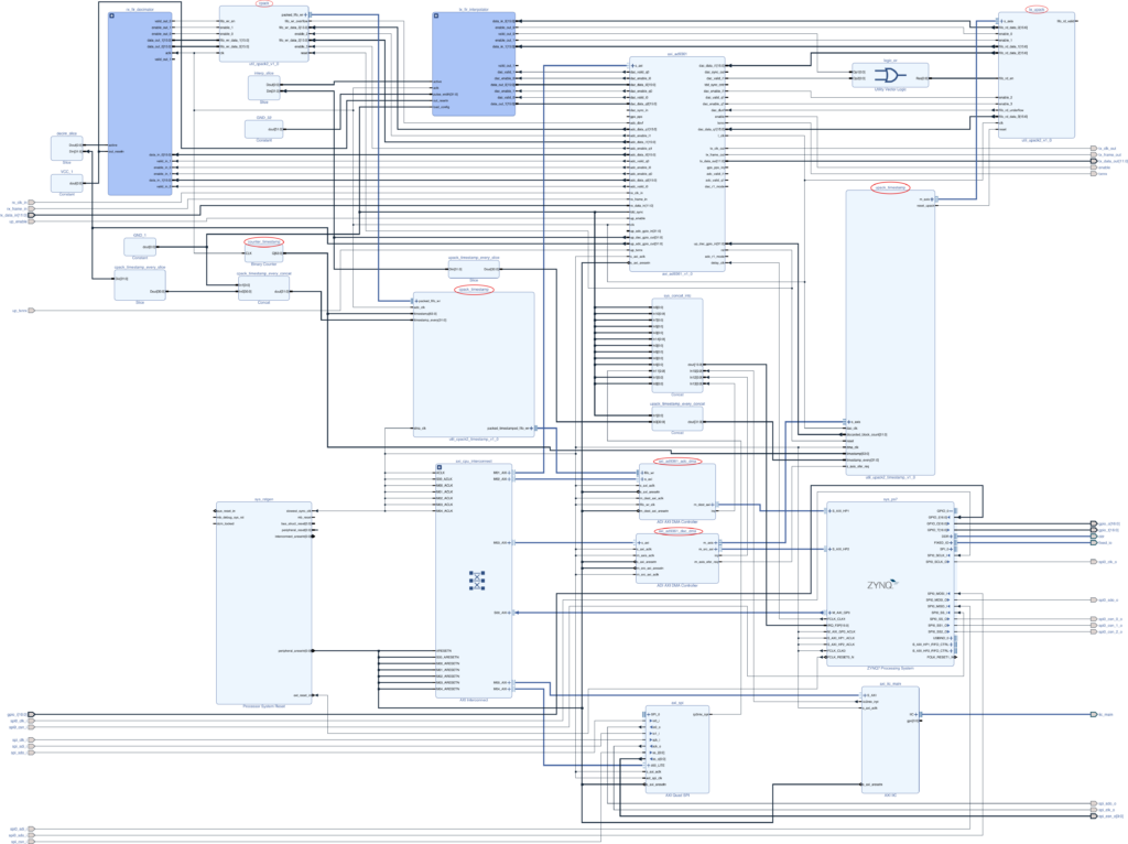
Common to both the transmit and receive path is the timestamp counter module counter_timestamp, a simple counter incremented on each rising edge of the ADC / DAC sample clock.
Considering the receive path, the axi_ad9361 module, corresponding to the interface module in Analog’s high level diagram is responsible for interfacing with the transceiver. It outputs samples on its four adc_data ports on each rising edge of the sample clock, with each port representing either the I or Q component of channel 0 or 1. Each data port has an enable and valid line associated with it, indicating whether the particular channel is in use / is presenting valid data to downstream modules.
Samples from the interface module pass into the cpack module. This module accepts the four data streams from the interface module, along with the corresponding enable signals. It’s job is to pack samples into 64-bit blocks, for transmission by the DMA controller. As part of this process it considers the channel enable signals. If a single I or Q channel is enabled, the module will pack four 16-bit ADC samples into a 64-bit DMA word. If I and Q channels were enabled for one of the two receive channels the module would pack two 32-bit ADC samples (consisting of two 16-bit values) into a 64-bit DMA word.
In Analog’s original design the output of the cpack module was connected directly to the axi_ad9361_adc_dma DMA controller. In the updated design a new module cpack_timestamp sits between the cpack and axi_ad9361_adc_dma modules. The module is relatively simple, accepting the 64-bit data bus from the cpack module, along with a 64-bit timestamp and 32-bit timestamp_every signal. The module counts the incoming samples, inserting a 64-bit timestamp into the outbound data bus whenever the counter reaches the value specified by timestamp_every. Typically timestamp every will be set to match the DMA buffer size, such that it will be inserted at the start of each buffer. Synchronisation signals pass between the cpack and axi_ad9361_adc_dma module informing the DMA controller of when the data stream is in sync. Thereby ensuring that when a transfer starts the timestamp will always appear at the start of the buffer.
The transmit path is largely a mirror image of the receive path. In Analog’s original design the output of the axi_ad9361_dac_dma DMA controller was connected directly to the upack module. In the updated design a new module upack_timestamp sits between the axi_ad9361_dac_dma and upack modules. The module works similarly to its counterpart, accepting the 64-bit data bus from the axi_ad9361_dac_dma module, along with a 64-bit timestamp and 32-bit timestamp_every signal. The module counts the incoming samples, expecting a 64-bit timestamp whenever the counter reaches the value specified by timestamp_every. When a timestamp is to be expected the module compares the timestamp in the data stream with the timestamp input. Pausing the transfer until the timestamp is reached by applying back-pressure to the DMA controller interface. While forcing the module outputs to zero. When the timestamp is reached the data is passed to the upack for re-arranging and onward transfer to the transceiver. If a block of samples arrive late (the time represented by the timestamp is found to have already passed), the module simply discards the block without passing it to the upack module. Slightly crude I know….but ideally samples will arrive either on time, or ahead of time. So the number of discarded blocks should be low 😅. A better scheme may be to track the timestamp and discard only those samples from the block which are late.
The timestamp_every signals are connected to general purpose IO connections on the RF transceiver interface, allowing them to be configured in software. The unit will behave identically to a stock ADALM-PLUTO until the new timestamping features are enabled.
The additional modules have been incorporated as part of a new IP library, with integrated test harnesses. Added as a git submodule alongside the Analog HDL code.
Low Latency USB Gadget Daemon
The ADALM-PLUTO’s USB interface is very flexible. The Zynq features an on-the-go (OTA) compatible USB controller, which may act as either as a USB host or USB device.
In host mode it allows the unit to interface with devices such as USB ethernet adapters. Allowing the device’s services to be accessed over a network.
In device mode the unit makes use of Linux’s USB Gadget API to implement a composite USB device, providing a collection of services to the host machine. These include a virtual serial port, allowing the device’s console to be accessed. A virtual network adapter allowing network services on the unit to be accessed, such as SSH. A virtual disk drive allowing documentation to be accessed and configuration/updates to be managed. Finally a custom interface allows industrial input/output (IIO) services to be accessed.
IIO appears to be an Analog initiative. Integrated into the mainline Linux kernel it allows devices such as inertial measurement units, analog to digital converters and digital to analog converts to be configured and managed by Linux. The Analog RF transceiver is configured and has data transfers managed via the IIO subsystem. The subsystem itself may be accessed via three means. Either locally, for applications running on the ADALM-PLUTO itself. Or remotely via IP or USB. Both the IP and USB interfaces are handed by a dedicated system service, the IIO daemon. The daemon interacts with the USB Gadget API, implementing a custom USB interface which the host may use to communicate directly. Given the level of functionality provided by the daemon it contains a complex parser which commands and data pass through on their way to the kernel IIO subsystem.
In my initial testing it appeared that the IIO daemon may have been the culprit for the poor performance noted.
I’d initially considered trying to improve the performance of the daemon but considered that it may be easier and faster to implement a separate daemon focused specifically on low latency, high bandwidth data transfers. While using the original IIO daemon to perform the required configuration of the device before data transfer begins.
Once configured the new daemon takes over. Making use of the local IIO interface, combined with the USB Gadget API to handle IQ sample transfers between the host and transceiver.
The daemon is implemented based on the asynchronous IO example provided with the Linux kernel source. Without digging too much into the USB and IIO interface specifics, the daemon contains two threads. One reads blocks of samples from the USB interface and writes them to the local IIO interface. The other does the opposite, reading blocks of samples from the local IIO interface and writing them to the USB interface. Asynchronous IO is used for both transmission and reception on the USB interface, allowing multiple USB transfers to be queued in both directions. The blocks are prepared such that they can be passed directly to / from the IIO interface without any conversion or reformatting required. As such the new daemon doesn’t need to have any knowledge of the timestamping mechanism employed, or the format of the data samples. It’s simply told how large a buffer to create before it starts copying blocks of data back and forth between the transceiver and host machine.
The new daemon is integrated into the firmware image of the ADALM-PLUTO such that it starts with the other system services. At the same time, to ensure the new features are easily verifiable the device name reported to the host has been updated to include a mention of the timestamping support.
Look out for a separate article related to the development of the USB gadget daemon. It was originally developed on a Raspberry PI which also features an OTG capable USB controller. Unlike the ADALM-PLUTO however it includes the required development tools to quickly rebuild and re-deploy the daemon for testing, making for a slightly quicker development cycle.
SoapySDR Driver Updates
SoapySDR is a vendor and platform neutral SDR support library. Applications wishing to access SDR devices may link to it, allowing them to access a range of devices using a standard interface. Vendors are then free to implement plugin modules to support their specific hardware. srsRAN supports SoapySDR and there exists a plugin for the ADALM-PLUTO. Following my goal of maintaining the original behaviour of the ADALM-PLUTO, the plugin was extended to make optional use of the new low latency daemon as well as allowing the timestamping feature to be configured. These options are passed to the module at construction time, allowing it to change its behaviour appropriately. Timestamping support is only implemented when the new daemon interface is selected. During development I briefly added support for timestamping via the original IIO interface, which helped confirm the IIO daemon performance issues. With only limited testing the original timestamping code was backed out, leaving only the new interface.
Having updated the plugin, SoapySDR’s python integration was used to test the new timestamping support. The RF transceiver supports a digital loopback mode, such that any transmitted IQ samples are echoed back to the host as received samples. A test script was created which made use of this mode to receive blocks of data from the SDR. Scheduling a transmission some time in the future. The transmission timestamp was encoded in the IQ samples such that it can be recovered and compared to the receive timestamp in the future. Likewise the receive timestamp itself is checked, ensuring it increases by the block size at each transfer.
Repositories
Various GitHub repositories have been forked in order to add timestamping support.
Analog ADALM-PLUTO Firmware – Top level repository which integrate the Linux kernel, Buildroot based root filesystem and HDL repositories. This repository may be used with the instructions from Analog’s wiki to rebuild the runtime and update images if required. At the time of writing the updates were based on the latest firmware release (V0.37).
Analog HDL – Analog’s HDL repository. While no changes were required to the Analog HDL modules, the ADALM-PLUTO’s project required updates to integrate the new modules.
Analog Buildroot – Analog’s Buildroot repository for the ADALM-PLUTO. With the new low latency USB gadget daemon integrated as a custom package.
Pluto HDL Quantulum – New repository containing additional HDL modules. Included as a submodule in the top level firmware repository.
Pluto SDR USB Gadget – New repository containing the low latency USB Gadget daemon.
SoapyPlutoSDR – Fork of the SoapySDR plugin for the Analog ADALM-PLUTO, with support for the low latency daemon and timestamping.
Building
If you’re just looking to try, skip ahead to the next section. I’ve released some pre-built images on GitHub. The following notes are adapted from Analog’s wiki.
Building the ADALM-PLUTO’s firmware requires installation of Xilinx’s Vivado Design Suite 2021.2. After which the firmware may be cloned and build as follows:
git clone --branch v0.37_timestamp --recurse-submodules --shallow-submodules https://github.com/pgreenland/plutosdr-fw.git
cd plutosdr-fw
export CROSS_COMPILE=arm-linux-gnueabihf-
export PATH=$PATH:/opt/Xilinx/Vitis/2021.2/gnu/aarch32/lin/gcc-arm-linux-gnueabi/bin
export VIVADO_SETTINGS=/opt/Xilinx/Vivado/2021.2/settings64.sh
make
Once complete (it takes a while) build artefacts will be available in the build directory. The two key images being pluto.dfu the RAM bootable image and pluto.frm the firmware update image.
Firmware Booting / Upgrade
The ADALM-PLUTO provides several options for booting the updated firmware. The following were adapted from Analog’s wiki.
If you’ve skipped ahead prebuilt images are available on GitHub, or you can build from source as described above if you prefer.
Booting from RAM
If you’re interested in testing the image before flashing it, you can boot the firmware from RAM using the device firmware update (DFU) mechanism.
For this the pluto.dfu file will be required, along with the dfu-tool, available in Debian and Ubuntu via the fwupd package.
- Enter DFU mode, by either:
- Holding user button next to the USB ports with a paperclip while connecting USB cable for power / data transfer.
- Allowing Pluto to boot, then connecting via it’s virtual serial console. Logging in with the username
rootand passwordanalog. Then issuing the commandpluto_reboot ramwhich will cause the device to reboot into DFU mode.
- Having entered DFU mode, load and boot the image with dfu-tool. You may need to run these command as root to gain access to the USB device, or find/create the appropriate udev rules to set the device permissions correctly.
dfu-util -d 0456:b673,0456:b674 -a firmware.dfu -D pluto.dfudfu-util -d 0456:b673,0456:b674 -a firmware.dfu -e
- Once booted the device should re-enumerate on the host as a USB device with the name
Analog Devices, Inc. PlutoSDR (ADALM-PLUTO) with timestamp support, indicating that the new firmware has booted successfully.
Flashing
Having tested the image using the DFU booting method described above. If you’d like to flash it to the device the builtin mass storage based update method can be used. This method is exactly the same as the regular update process.
Simply drag and drop the pluto.frm file into the virtual mass storage device and unmount it. After which the LED on the device will begin flashing rapidly while the update is performed. Once the update is complete the device will reboot into the new firmware version.
The device should now always boot and enumerate with the new name Analog Devices, Inc. PlutoSDR (ADALM-PLUTO) with timestamp support. Indicating the firmware with timestamping support is installed.
Note: Remember not to disconnecting the USB while the LED is blinking rapidly, indicating the firmware update is in-progress as this risks corrupting the firmware.
If you with to return to the official Analog firmware at any time, the same mechanism may be used, with your chosen version of the official release.
ADALM-PLUTO Configuration
I wasn’t quite sure where to include the following optional notes. There are some configuration items which are managed by the u-boot bootloader used by the ADALM-PLUTO and applied at boot time.
The two we’re interested in control whether the second CPU core in the Zynq is active. Along with the external clock configuration of the device. The full list of environment variables are listed in Analog’s wiki.
They’re optional but recommended. If applied having booted from RAM you’ll need to reboot the unit from RAM again having applied them (sorry).
Second CPU Core
Depending on the hardware revision of your board the Zynq part included in the device may either be the single or dual core variant. My fairly recent revision D unit contains the dual core version. Out of the box dual core versions have their second core disabled to mimic their single core brethren. The new USB gadget attempts to lock its TX thread to one core and RX thread to the other, therefore it expects to be run on a dual core configuration. However it shouldn’t fail if it isn’t able to complete the thread affinity assignments.
To enable the second core:
- Connect to the serial console.
- Login with the username
rootand passwordanalog. - Issue the command:
fw_setenv maxcpus 2- Which will add a parameter maxcpus to the u-boot environment, causing the second CPU core to be brought online on next boot.
External Clock Configuration
The ADALM-PLUTO contains a 40Mhz oscillator which supplies the RF transceiver with a reference for its internal phase locked loops, used to generate the RF carriers and sample clocks. The full schematic and bill of materials is available in Analog’s wiki. The oscillator used is a Rakon 513371 with an accuracy of +/- 25ppm. This is some way outside the LTE technical specification 36.104, which allows a maximum of +/- 0.25ppm in its most relaxed configuration.
I found during testing that some user equipment was happy with the Pluto’s signal, others not so much. For example my trusty old Sierra Wireless MC7455 was quite happy, it found, registered with and began using the network.
A newer Quectel EM12 module based around a Qualcomm platform however either didn’t see the network. Or when it did refused to connect to it.
The revision D version of the ADALM-PLUTO that I have allows for an external reference clock to be suppled and used in preference to the internal oscillator.
While it exposes a pair of SMA connects for transmit and receive externally, it contains a number of additional UFL connectors internally. Allowing the transceivers additional channels to be accessed as well as an external reference to be suppled.
With a little bit of help from the 3D printer I created a new face place, which allows the additional connections to be exposed on the front panel with the existing transmit and receive connectors.
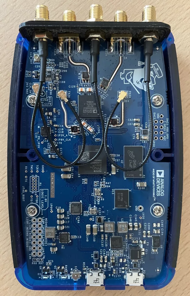
The external clock connection is routed to the centre SMA connector.
The STL and OpenSCAD source files for the updated front panel, adapted from the original CAD found on Analog’s Wiki (See Rev B 3D Model) may be downloaded here. As it so happens the ADALM-PLUTO uses an off-the-shelf case from Hammond Manufacturing…must resist temptation to swap out the case.
Once the the external clock connection has been made accessible the next step is supplying an appropriate clock signal before updating the clock configuration to use the external clock.
I opted to make use of a GPS disciplined oscillator (GPSDO), which I understand is the method used by commercial LTE equipment and lots of other hardware which requires a low cost but precise clock source.
The ADALM-PLUTO should accept an external reference clock in the range of 10Mhz to 80Mhz. I initially tried to use a 10Mhz clock which my GPSDO was already configured for. Unfortunately it seems that the clock buffer chip isn’t all that happy receiving with a square wave at this frequency. It is however happy at 20Mhz. If your clock source produces a sine wave, 10Mhz should (apparently) work but I’ve not found that to be the case myself.
I thought for a moment that I’d killed the LTC6957HMS-3 clock buffer chip that the external clock input feeds. The PCB has a note that the external reference shouldn’t exceed 3.3v…which I dont believe I did. However reading on Analog’s forums it seems that the chip possibly shouldn’t have an input signal present when its supplies are off. I’ve done this quite a few times now 🙈.
I got concerned after seeing timeout errors in the kernel log as the device was booting. Upon further investigation there was no output on the clk_out UFL connection on the board, which is the second buffered output of the chip.
While flapping around online trying to find a replacement (gotta love the parts shortage), the chip seemingly recovered, presenting the clock output on the scope again. Lesson learnt, go real careful with the external clock input – it may be rather sensitive.
The external clock is again configured through the u-boot environment. To configure and select the external clock source:
- Connect to the serial console.
- Login with the username
rootand passwordanalog. - Issue the commands:
fw_setenv refclk_source external- Which will switch from the internal to external reference clock.
fw_setenv ad936x_ext_refclk_override '<20000000>'- Which will specify a 20Mhz reference clock. Note that the angular brackets are required and in turn the quotes are required to ensure the terminal doesn’t attempt to interpret the brackets itself.
- If you’d like to return to the internal clock source, issue the commands:
fw_setenv refclk_source internal- Which will switch from the external to internal reference clock.
fw_setenv ad936x_ext_refclk_override- Remove the reference clock frequency definition.
ADALM-PLUTO Hardware Setup
The hardware setup used with the ADALM-PLUTO is inspired by the previous setup I used with the LimeSDR:
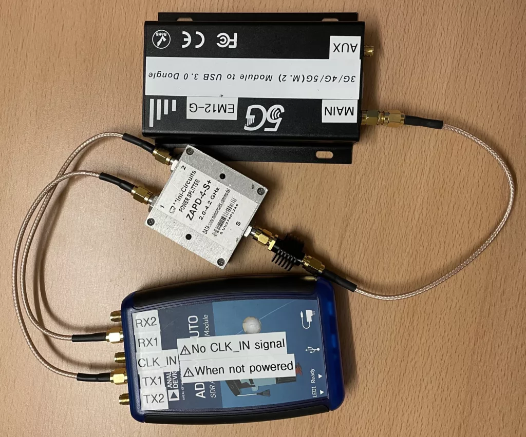
A power splitter and attenuator separate the TX and RX signals while protecting the SDR and UE from each other’s power amplifiers.
Building srsRAN and Supporting Libraries
I’ve described how to build srsRAN before, when experimenting with the LimeSDR. For for a more detailed version of the following see Private LTE with LimeSDR and srsRAN – Part 1 (Software).
In order to isolate the build, cmake is being provided with updated prefix and install prefix paths, such that it will install the required libraries and tools in a user specified location.
To allow this location to be customised, set an environment variable:
export SRSRAN_INSTALL=${HOME}/srsRAN
SoapySDR
To build the SoapySDR library itself:
sudo apt-get install cmake g++ libpython3-dev python3-numpy swig
git clone --branch soapy-sdr-0.8.1 https://github.com/pothosware/SoapySDR.git
cd SoapySDR
mkdir build && cd build
cmake -DCMAKE_PREFIX_PATH=${SRSRAN_INSTALL} -DCMAKE_INSTALL_PREFIX=${SRSRAN_INSTALL} ..
make -j`nproc` && make install
SoapySDR Pluto Plugin
To build the updated SoapySDR plugin for the ADALM-PLUTO which supports the low latency daemon and timestamping.
First we need LibIIO and LibAD3961. Ideally I’d have installed these from my distribution’s package manager. However Ubuntu 20.04’s repositories doesn’t contain the required 0.24 release of IIO. Therefore I opted to build these from source.
To build LibIIO:
sudo apt-get install libxml2 libxml2-dev bison flex libcdk5-dev cmake
sudo apt-get install libusb-1.0-0-dev libaio-dev
git clone --branch v0.24 https://github.com/analogdevicesinc/libiio.git
cd libiio
mkdir build && cd build
cmake -DCMAKE_PREFIX_PATH=${SRSRAN_INSTALL} -DCMAKE_INSTALL_PREFIX=${SRSRAN_INSTALL} -DUDEV_RULES_INSTALL_DIR=${SRSRAN_INSTALL}/etc/udev/rules.d -DHAVE_DNS_SD=OFF ..
make -j`nproc` && make install
To build LibAD3961-IIO:
git clone --branch v0.3 https://github.com/analogdevicesinc/libad9361-iio.git
cd libad9361-iio
mkdir build && cd build
cmake -DCMAKE_PREFIX_PATH=${SRSRAN_INSTALL} -DCMAKE_INSTALL_PREFIX=${SRSRAN_INSTALL} ..
make -j`nproc` && make install
To build the ADALM-PLUTO SoapySDR plugin:
git clone --branch sdr_gadget_timestamping https://github.com/pgreenland/SoapyPlutoSDR.git
cd SoapyPlutoSDR
mkdir build && cd build
cmake -DCMAKE_PREFIX_PATH=${SRSRAN_INSTALL} -DCMAKE_INSTALL_PREFIX=${SRSRAN_INSTALL} ..
make -j`nproc` && make install
Having installed everything to an unprivileged directory. There is one file which needs to be installed as root. The udev rules allowing the device to be accessed without root privileges. This can be added via:
echo 'SUBSYSTEM=="usb", ATTR{idVendor}=="0456", ATTR{idProduct}=="b673", MODE="666"' | sudo tee /etc/udev/rules.d/90-libiio_pluto.rules
sudo udevadm control --reload-rules && sudo udevadm trigger
srsRAN
To build srsRAN:
sudo apt-get install build-essential cmake libfftw3-dev libmbedtls-dev libboost-program-options-dev libconfig++-dev libsctp-dev
git clone --branch release_23_04 https://github.com/srsran/srsRAN_4G.git
cd srsRAN_4G
mkdir build && cd build
cmake -DCMAKE_PREFIX_PATH=${SRSRAN_INSTALL} -DCMAKE_INSTALL_PREFIX=${SRSRAN_INSTALL} -DUSE_LTE_RATES=ON ..
make -j`nproc` && make install
./srsran_install_configs.sh user
srsRAN Configuration & Launch
The final command in the srsRAN build notes above will have installed a copy of the reference configuration files into your home directory at ~/.config/srsran.
Edit ~/.config/srsran/enb.conf:
In the [enb] section, update:
n_prbto 6.
In the [rf] section, update:
tx_gainto 89.rx_gainto 20.
Add the following to the end of the section:
device_name = soapy
device_args = driver=plutosdr,usb_direct=1,timestamp_every=1920,loopback=0
time_adv_nsamples = 40
Edit ~/.config/srsran/rr.conf:
In the cell_list modify the first entry, updating:
dl_earfcnto 1575- Note the above will cause the unit to transmit in band 3. If like me you have a low end spectrum analyser and want to take a look. A better choice may be 2525 which will select band 5, placing the downlink at 881Mhz.
Edit ~/.config/srsran/sib.conf:
In the sib2 section, updating:
prach_freq_offsetto 0.
Edit .config/srsran/user_db.csv, providing your SIM card details. For more information on this see Private LTE with LimeSDR and srsRAN – Part 3 (SIM Cards) and Private LTE with LimeSDR and srsRAN – Part 4 (Config & Launch).
To launch srsRAN, assuming it was built and installed as described above.
First start the EPC application:
sudo LD_LIBRARY_PATH=${SRSRAN_INSTALL}/lib sh -c "cd ${HOME}/.config/srsran; ${SRSRAN_INSTALL}/bin/srsepc epc.conf"
Then start the eNodeB application:
echo "performance" | sudo tee /sys/devices/system/cpu/cpu*/cpufreq/scaling_governor
sudo LD_LIBRARY_PATH=${SRSRAN_INSTALL}/lib sh -c "cd ${HOME}/.config/srsran; ${SRSRAN_INSTALL}/bin/srsenb enb.conf"
If all goes well your user equipment should now be able to find and register on the network.
Testing
iperf3
For initial testing, the goto tool was of course iperf….we’re all about speed here.
On the machine with the ADALM-PLUTO (hosting the mobile network):
iperf3 -s
On the machine with the user equipment (in this case a Quectel EM12):
iperf3 -c 172.16.0.1 -t 10 -R
Which resulted in the following encouraging trace:
Connecting to host 172.16.0.1, port 5201
Reverse mode, remote host 172.16.0.1 is sending
[  5] local 172.16.0.3 port 32884 connected to 172.16.0.1 port 5201
[ ID] Interval           Transfer     Bitrate
[  5]   0.00-1.00   sec   554 KBytes  4.54 Mbits/sec
[  5]   1.00-2.00   sec   550 KBytes  4.51 Mbits/sec
[  5]   2.00-3.00   sec   546 KBytes  4.47 Mbits/sec
[  5]   3.00-4.00   sec   547 KBytes  4.48 Mbits/sec
[  5]   4.00-5.00   sec   551 KBytes  4.52 Mbits/sec
[  5]   5.00-6.00   sec   543 KBytes  4.45 Mbits/sec
[  5]   6.00-7.00   sec   549 KBytes  4.49 Mbits/sec
[  5]   7.00-8.00   sec   551 KBytes  4.52 Mbits/sec
[  5]   8.00-9.00   sec   544 KBytes  4.46 Mbits/sec
[  5]   9.00-10.00  sec   272 KBytes  2.22 Mbits/sec
- - - - - - - - - - - - - - - - - - - - - - - - -
[ ID] Interval           Transfer     Bitrate         Retr
[  5]   0.00-10.05  sec  6.80 MBytes  5.67 Mbits/sec   39             sender
[  5]   0.00-10.00  sec  5.09 MBytes  4.27 Mbits/sec                  receiver

iperf Done.
Not too shabby at ~4Mbit/s.
Testing the upload by dropping the -R option:
Connecting to host 172.16.0.1, port 5201
[  5] local 172.16.0.3 port 57340 connected to 172.16.0.1 port 5201
[ ID] Interval           Transfer     Bitrate         Retr  Cwnd
[  5]   0.00-1.00   sec   443 KBytes  3.62 Mbits/sec    0   42.4 KBytes
[  5]   1.00-2.00   sec   255 KBytes  2.09 Mbits/sec    0   52.3 KBytes
[  5]   2.00-3.00   sec   255 KBytes  2.09 Mbits/sec    0   63.6 KBytes
[  5]   3.00-4.00   sec   191 KBytes  1.56 Mbits/sec    0   73.5 KBytes
[  5]   4.00-5.00   sec   382 KBytes  3.13 Mbits/sec    0   89.1 KBytes
[  5]   5.00-6.00   sec   255 KBytes  2.08 Mbits/sec    0    126 KBytes
[  5]   6.00-7.00   sec   318 KBytes  2.61 Mbits/sec    0    175 KBytes
[  5]   7.00-8.00   sec   891 KBytes  7.30 Mbits/sec    0    242 KBytes
[  5]   8.00-9.00   sec   636 KBytes  5.21 Mbits/sec    0    322 KBytes
[  5]   9.00-10.00  sec   891 KBytes  7.30 Mbits/sec    0    426 KBytes
- - - - - - - - - - - - - - - - - - - - - - - - -
[ ID] Interval           Transfer     Bitrate         Retr
[  5]   0.00-10.00  sec  4.41 MBytes  3.70 Mbits/sec    0             sender
[  5]   0.00-10.12  sec  2.04 MBytes  1.69 Mbits/sec                  receiver

iperf Done.
Again not bad at ~1.7Mbit/s.
Vivado Integrated Logic Analyser
Given the long pipeline of software, hardware, more software and yet more hardware that IQ samples have to travel between srsRAN and the RF transceiver, I’d wondered how much timestamp headroom there would be. For example how long from when samples arrive at the upack_timestamp module to when they’re due to be transmitted.
Making use of Vivado’s Integrated Logic Analyser feature, an FPGA image augmented with debug signals taken from the transmit path and the appropriate Xilinx JTAG adapter I was able to take a look.
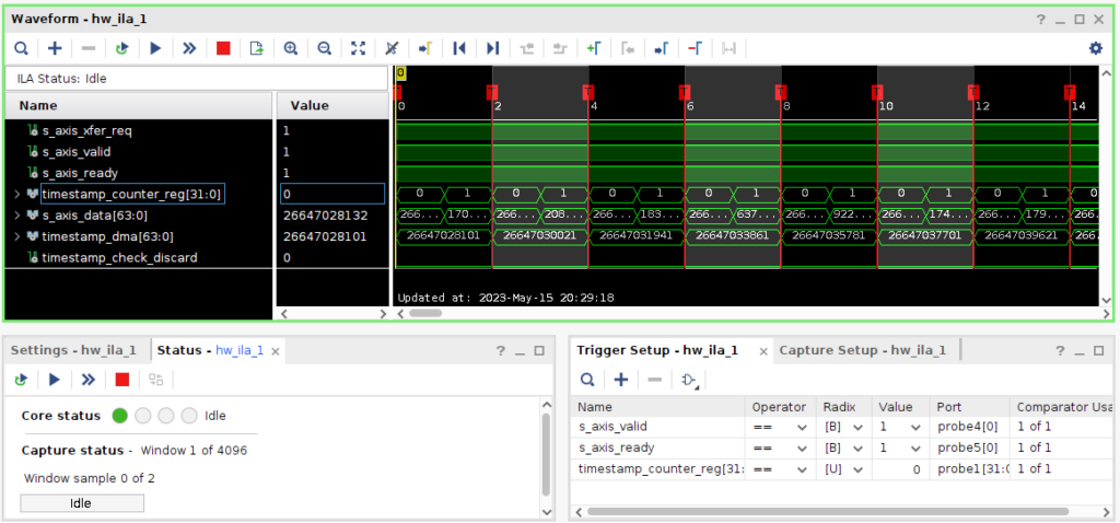
To check things were working, I configured the triggers to capture the start of block timestamps as they passed through the upack2_timestamp module:
Looking pretty much as expected, with timestamps being presented when the timestamp_counter_reg rolls over to zero and AXI bus signals indicate data is available to read.
Next, tweaking the triggers to look for discarded blocks, i.e. blocks arriving late, with timestamps in the past.
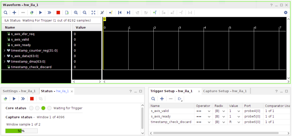
To my surprise, the logger never triggered. It seems that everything is able to keep up….not sure why but I’m pleasantly surprised.
With no dropped blocks I got to wondering how much headroom there actually is, i.e. how long samples arrive before they’re destined for transmission.
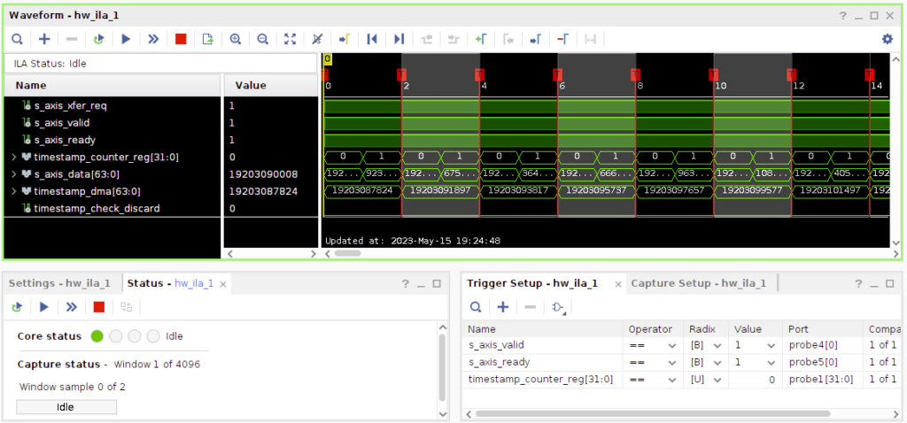
With the network operating normally, I re-ran the original setup capturing block timestamps.
The headroom here would be the difference between timestamp_dma the sample counter synchronised into in the DMA controller clock domain and s_axis_data, the first 64-bit value of a block arriving from the DMA controller.
Considering the example above, subtracting one timestamp from the other yields 31. Which at a sample rate of 1.92Mhz results in the princely sum of 16uS. Feels a bit tight, but seems to work. Exporting the data to excel and performing the same calculation on each trigger point seems resulted in a constant value of 31 in each of the captures above.
Going Faster?
Given that things appear to be stable at the lowest number of LTE resource blocks, can we take the next step from 6 to 15 blocks? It appears we can 😀.
Edit ~/.config/srsran/enb.conf:
In the [enb] section, update:
n_prbto 15.
In the [rf] section, update:
device_args = driver=plutosdr,usb_direct=1,timestamp_every=3840,loopback=0
Edit ~/.config/srsran/sib.conf:
In the sib2 section, updating:
prach_freq_offsetto 4.
Restarting eNodeB and we’re away 😀.
Repeating the iperf3 tests in both directions, first download:
Connecting to host 172.16.0.1, port 5201
Reverse mode, remote host 172.16.0.1 is sending
[  5] local 172.16.0.4 port 56352 connected to 172.16.0.1 port 5201
[ ID] Interval           Transfer     Bitrate
[  5]   0.00-1.00   sec  1.62 MBytes  13.6 Mbits/sec
[  5]   1.00-2.00   sec  1.63 MBytes  13.7 Mbits/sec
[  5]   2.00-3.00   sec  1.05 MBytes  8.79 Mbits/sec
[  5]   3.00-4.00   sec  1.66 MBytes  13.9 Mbits/sec
[  5]   4.00-5.00   sec  1.63 MBytes  13.7 Mbits/sec
[  5]   5.00-6.00   sec  1.62 MBytes  13.6 Mbits/sec
[  5]   6.00-7.00   sec  1.64 MBytes  13.8 Mbits/sec
[  5]   7.00-8.00   sec  1.63 MBytes  13.7 Mbits/sec
[  5]   8.00-9.00   sec  1.63 MBytes  13.7 Mbits/sec
[  5]   9.00-10.00  sec  1.62 MBytes  13.6 Mbits/sec
- - - - - - - - - - - - - - - - - - - - - - - - -
[ ID] Interval           Transfer     Bitrate         Retr
[  5]   0.00-10.06  sec  17.6 MBytes  14.7 Mbits/sec  258             sender
[  5]   0.00-10.00  sec  15.7 MBytes  13.2 Mbits/sec                  receiver

iperf Done.
Then upload:
Connecting to host 172.16.0.1, port 5201
[  5] local 172.16.0.4 port 54628 connected to 172.16.0.1 port 5201
[ ID] Interval           Transfer     Bitrate         Retr  Cwnd
[  5]   0.00-1.00   sec   881 KBytes  7.21 Mbits/sec    0   63.6 KBytes
[  5]   1.00-2.00   sec   764 KBytes  6.25 Mbits/sec    0   96.2 KBytes
[  5]   2.00-3.00   sec   764 KBytes  6.25 Mbits/sec    0    129 KBytes
[  5]   3.00-4.00   sec   954 KBytes  7.82 Mbits/sec    0    163 KBytes
[  5]   4.00-5.00   sec   764 KBytes  6.25 Mbits/sec    0    195 KBytes
[  5]   5.00-6.00   sec   891 KBytes  7.30 Mbits/sec    0    228 KBytes
[  5]   6.00-7.00   sec   509 KBytes  4.17 Mbits/sec    0    260 KBytes
[  5]   7.00-8.00   sec  1.12 MBytes  9.39 Mbits/sec    0    296 KBytes
[  5]   8.00-9.00   sec   700 KBytes  5.73 Mbits/sec    0    382 KBytes
[  5]   9.00-10.00  sec   827 KBytes  6.78 Mbits/sec    0    392 KBytes
- - - - - - - - - - - - - - - - - - - - - - - - -
[ ID] Interval           Transfer     Bitrate         Retr
[  5]   0.00-10.00  sec  8.01 MBytes  6.72 Mbits/sec    0             sender
[  5]   0.00-10.06  sec  6.40 MBytes  5.33 Mbits/sec                  receiver

iperf Done.
Can we go even faster?…..sadly not. The next step from 15 to 25 resource blocks doubles the sample rate again. This pushes the data bitrate from:
(3840 samples + 2 timestamp samples per block) * 4 bytes per sample * 1000 blocks per second = 15,007KB/s (14.66MB/s).
To 30015KB/s (29.31MB/s).
USB2 operates at 480Mbit/s, which equates to 60MB/s. Given that it’s half-duplex, before considering any protocol overheads, we’re almost certain to exceed the available bandwidth.
Conclusion
This project started its life while waiting for a parcel to arrive for another project as many projects do. I’d wondered how hard it might be to get the ADALM-PLUTO working properly with srsRAN after my initial attempt failed. The thought of how hard can it be crossed my mind, as it turns out quite hard. The parcel arrived in a week, but it took around 3 months of evenings and weekends to implement and test the various chunks of Verilog and C required to “just add timestamps”. Did I learn a lot along the way? Yes. Would I do it again? No…well…O.K. …probably yes.
As with all my projects the code developed is on GitHub, see the links above. If you give it a try drop me a comment, I’d be interested to hear how you get on!
Development Notes
The following usually end up stuffed in a readme somewhere. Given the number of repositories involved in this project I couldn’t decide which one to stash them in, so here they are…
If you’re tinkering with the ADALM-PLUTO’s HDL yourself the following may be useful to rebuild just the HDL code and re-integrate into a device firmware upgrade (DFU) image:
source /opt/Xilinx/Vivado/2021.2/settings64.sh
make -C hdl/projects/pluto && cp hdl/projects/pluto/pluto.sdk/system_top.xsa build/system_top.xsa
make build/pluto.dfu
Making use of SoapySDRUtil to find, probe and instantiate an instance of the ADALM-PLUTO SDR plugin:
export BASE_PATH=${HOME}/srsRAN
export LD_LIBRARY_PATH=${BASE_PATH}/lib:/usr/local/lib
export PATH=${BASE_PATH}/bin:$PATH
export PYTHONPATH=${BASE_PATH}/lib/python3.8/site-packages

SoapySDRUtil --find
SoapySDRUtil --probe="driver=plutosdr"
SoapySDRUtil --make="driver=plutosdr"
SoapySDRUtil --make="driver=plutosdr,uri=usb:,usb_direct=1,loopback=1,timestamp_every=1920"
Tweaking the ADALM-PLUTO’s buildroot configuration:
make -C buildroot ARCH=arm zynq_pluto_defconfig
make -C buildroot ARCH=arm menuconfig
make -C buildroot ARCH=arm savedefconfig
make
Building and running C version of timestamp loopback test:
cd SoapyPlutoSDR/support/test_c
mkdir build && cd build
cmake -DCMAKE_PREFIX_PATH=${HOME}/srsRAN ..
make
./test_timestamp_loopback >test.log 2>&1
An example of the expected output from the test:
[WARNING] Unable to scan ip: -19
[INFO] Opening URI usb:...
[INFO] USB direct mode enabled!
[INFO] digital loopback enabled
[INFO] RX timestamping enabled, every 1920 samples
[INFO] TX timestamping enabled, every 1920 samples
[INFO] Using format CS16.
[INFO] Has direct RX copy: 1
[INFO] Using format CS16.
[INFO] Has direct TX copy: 1
[WARNING] Failed to set RX thread priority (1)
[WARNING] Failed to set TX thread priority (1)
Selected URI: usb:
Selected channels: 1
Selected buffer count: 10000
MTU - TX: 1920, RX: 1920
Start test...
Buffer: 0 - Samples: 1920, Flags: 4, Time: 4419247873958, TimeDiff: 4419247873958
Buffer: 1 - Samples: 1920, Flags: 4, Time: 4419248873958, TimeDiff: 1000000
Buffer: 2 - Samples: 1920, Flags: 4, Time: 4419249873958, TimeDiff: 1000000
Buffer: 3 - Samples: 1920, Flags: 4, Time: 4419250873958, TimeDiff: 1000000
Buffer: 4 - Samples: 1920, Flags: 4, Time: 4419251873958, TimeDiff: 1000000
Buffer: 5 - Samples: 1920, Flags: 4, Time: 4419252873958, TimeDiff: 1000000
Buffer: 6 - Samples: 1920, Flags: 4, Time: 4419253873958, TimeDiff: 1000000
Buffer: 7 - Samples: 1920, Flags: 4, Time: 4419254873958, TimeDiff: 1000000
Buffer: 8 - Samples: 1920, Flags: 4, Time: 4419255873958, TimeDiff: 1000000
Buffer: 9 - Samples: 1920, Flags: 4, Time: 4419256873958, TimeDiff: 1000000
Buffer: 10 - Samples: 1920, Flags: 4, Time: 4419257873958, TimeDiff: 1000000
...
Buffer: 9990 - Samples: 1920, Flags: 4, Time: 4429237873958, TimeDiff: 1000000
Buffer: 9991 - Samples: 1920, Flags: 4, Time: 4429238873958, TimeDiff: 1000000
Buffer: 9992 - Samples: 1920, Flags: 4, Time: 4429239873958, TimeDiff: 1000000
Buffer: 9993 - Samples: 1920, Flags: 4, Time: 4429240873958, TimeDiff: 1000000
Buffer: 9994 - Samples: 1920, Flags: 4, Time: 4429241873958, TimeDiff: 1000000
Buffer: 9995 - Samples: 1920, Flags: 4, Time: 4429242873958, TimeDiff: 1000000
Buffer: 9996 - Samples: 1920, Flags: 4, Time: 4429243873958, TimeDiff: 1000000
Buffer: 9997 - Samples: 1920, Flags: 4, Time: 4429244873958, TimeDiff: 1000000
Buffer: 9998 - Samples: 1920, Flags: 4, Time: 4429245873958, TimeDiff: 1000000
Buffer: 9999 - Samples: 1920, Flags: 4, Time: 4429246873958, TimeDiff: 1000000
Checking channel 0
Buffer 0 doesn't contain timestamp
Buffer 1 doesn't contain timestamp
Buffer 2 doesn't contain timestamp
Buffer 3 doesn't contain timestamp
Buffer 4 contains TX TS after 4 buffers, TX TS queue index 0, buffer word index 44
Buffer 5 contains TX TS after 1 buffers, TX TS queue index 1, buffer word index 44
Buffer 6 contains TX TS after 1 buffers, TX TS queue index 2, buffer word index 44
Buffer 7 contains TX TS after 1 buffers, TX TS queue index 3, buffer word index 44
Buffer 8 contains TX TS after 1 buffers, TX TS queue index 4, buffer word index 44
Buffer 9 contains TX TS after 1 buffers, TX TS queue index 5, buffer word index 44
Buffer 10 contains TX TS after 1 buffers, TX TS queue index 6, buffer word index 44
...
Buffer 9990 contains TX TS after 1 buffers, TX TS queue index 9986, buffer word index 44
Buffer 9991 contains TX TS after 1 buffers, TX TS queue index 9987, buffer word index 44
Buffer 9992 contains TX TS after 1 buffers, TX TS queue index 9988, buffer word index 44
Buffer 9993 contains TX TS after 1 buffers, TX TS queue index 9989, buffer word index 44
Buffer 9994 contains TX TS after 1 buffers, TX TS queue index 9990, buffer word index 44
Buffer 9995 contains TX TS after 1 buffers, TX TS queue index 9991, buffer word index 44
Buffer 9996 contains TX TS after 1 buffers, TX TS queue index 9992, buffer word index 44
Buffer 9997 contains TX TS after 1 buffers, TX TS queue index 9993, buffer word index 44
Buffer 9998 contains TX TS after 1 buffers, TX TS queue index 9994, buffer word index 44
Buffer 9999 contains TX TS after 1 buffers, TX TS queue index 9995, buffer word index 44
test complete!
Building and running Python version of timestamp loopback test (created when there appeared to be a bug in the C version that turned out to be a bug in the HDL):
export BASE_PATH=${HOME}/srsRAN
export LD_LIBRARY_PATH=${BASE_PATH}/lib:/usr/local/lib
export PYTHONPATH=${BASE_PATH}/lib/python3.9/site-packages
cd SoapyPlutoSDR/support/test_python
python3 test_timestamp_loopback.py >test.log 2>&1
Note for the tests above the u-boot variable xo_correction should be backed up before being set to 40Mhz, via fw_setenv xo_correction 40000000. Analog characterise the oscillators used on the boards during production, setting the xo_correction parameter to the measured clock frequency. When running the loopback tests this causes rounding errors then converting from the sample clock to wall clock. The easiest way of correcting this was found to temporarily disable the trim. Although after the tests the original value should be restored.
An example of the expected output from the test:
Selected URI: usb:
Selected channels: 1
Selected buffer count: 10000
[WARNING] Unable to scan ip: -19

[WARNING] Unable to scan ip: -19

[INFO] Opening URI usb:...
[INFO] USB direct mode enabled!
[INFO] digital loopback enabled
[INFO] RX timestamping enabled, every 1920 samples
[INFO] TX timestamping enabled, every 1920 samples
[INFO] Using format CS16.
[INFO] Has direct RX copy: 1
[INFO] Using format CS16.
[INFO] Has direct TX copy: 1
MTU - TX: 1920, RX: 1920
[WARNING] Failed to set RX thread priority (1)
[WARNING] Failed to set TX thread priority (1)
Start test...
Buffer: 0 - Samples: 1920, Flags: 4, Time: 3787286873958, TimeDiff: 3787286873958
Buffer: 1 - Samples: 1920, Flags: 4, Time: 3787287873958, TimeDiff: 1000000
Buffer: 2 - Samples: 1920, Flags: 4, Time: 3787288873958, TimeDiff: 1000000
Buffer: 3 - Samples: 1920, Flags: 4, Time: 3787289873958, TimeDiff: 1000000
Buffer: 4 - Samples: 1920, Flags: 4, Time: 3787290873958, TimeDiff: 1000000
Buffer: 5 - Samples: 1920, Flags: 4, Time: 3787291873958, TimeDiff: 1000000
Buffer: 6 - Samples: 1920, Flags: 4, Time: 3787292873958, TimeDiff: 1000000
Buffer: 7 - Samples: 1920, Flags: 4, Time: 3787293873958, TimeDiff: 1000000
Buffer: 8 - Samples: 1920, Flags: 4, Time: 3787294873958, TimeDiff: 1000000
Buffer: 9 - Samples: 1920, Flags: 4, Time: 3787295873958, TimeDiff: 1000000
Buffer: 10 - Samples: 1920, Flags: 4, Time: 3787296873958, TimeDiff: 1000000
...
Buffer: 9990 - Samples: 1920, Flags: 4, Time: 3797276873958, TimeDiff: 1000000
Buffer: 9991 - Samples: 1920, Flags: 4, Time: 3797277873958, TimeDiff: 1000000
Buffer: 9992 - Samples: 1920, Flags: 4, Time: 3797278873958, TimeDiff: 1000000
Buffer: 9993 - Samples: 1920, Flags: 4, Time: 3797279873958, TimeDiff: 1000000
Buffer: 9994 - Samples: 1920, Flags: 4, Time: 3797280873958, TimeDiff: 1000000
Buffer: 9995 - Samples: 1920, Flags: 4, Time: 3797281873958, TimeDiff: 1000000
Buffer: 9996 - Samples: 1920, Flags: 4, Time: 3797282873958, TimeDiff: 1000000
Buffer: 9997 - Samples: 1920, Flags: 4, Time: 3797283873958, TimeDiff: 1000000
Buffer: 9998 - Samples: 1920, Flags: 4, Time: 3797284873958, TimeDiff: 1000000
Buffer: 9999 - Samples: 1920, Flags: 4, Time: 3797285873958, TimeDiff: 1000000
Checking channel 0
Buffer 0 doesn't contain timestamp
Buffer 1 doesn't contain timestamp
Buffer 2 doesn't contain timestamp
Buffer 3 doesn't contain timestamp
Buffer 4 contains TX TS after 4 buffers, TX TS queue index 0, buffer word index 44
Buffer 5 contains TX TS after 1 buffers, TX TS queue index 1, buffer word index 44
Buffer 6 contains TX TS after 1 buffers, TX TS queue index 2, buffer word index 44
Buffer 7 contains TX TS after 1 buffers, TX TS queue index 3, buffer word index 44
Buffer 8 contains TX TS after 1 buffers, TX TS queue index 4, buffer word index 44
Buffer 9 contains TX TS after 1 buffers, TX TS queue index 5, buffer word index 44
Buffer 10 contains TX TS after 1 buffers, TX TS queue index 6, buffer word index 44
...
Buffer 9990 contains TX TS after 1 buffers, TX TS queue index 9986, buffer word index 44
Buffer 9991 contains TX TS after 1 buffers, TX TS queue index 9987, buffer word index 44
Buffer 9992 contains TX TS after 1 buffers, TX TS queue index 9988, buffer word index 44
Buffer 9993 contains TX TS after 1 buffers, TX TS queue index 9989, buffer word index 44
Buffer 9994 contains TX TS after 1 buffers, TX TS queue index 9990, buffer word index 44
Buffer 9995 contains TX TS after 1 buffers, TX TS queue index 9991, buffer word index 44
Buffer 9996 contains TX TS after 1 buffers, TX TS queue index 9992, buffer word index 44
Buffer 9997 contains TX TS after 1 buffers, TX TS queue index 9993, buffer word index 44
Buffer 9998 contains TX TS after 1 buffers, TX TS queue index 9994, buffer word index 44
Buffer 9999 contains TX TS after 1 buffers, TX TS queue index 9995, buffer word index 44
test complete!
Reading ADC and DAC interface module GPIO registers which drive the timestamp_every signals:
#For HDL register access via IIO bit 31 needs to be set apparently, see: https://m.elecfans.com/article/1567353.html
#Read ADC/DAC
iio_reg -u 'local:' cf-ad9361-lpc 0x800000BC
iio_reg -u 'local:' cf-ad9361-dds-core-lpc 0x800000BC
#Write ADC/DAC
iio_reg -u 'local:' cf-ad9361-lpc 0x800000BC 0x780
iio_reg -u 'local:' cf-ad9361-dds-core-lpc 0x800000BC 0x780
Enabling digital loopback mode manually (handled by SoapySDR library now), see:
echo 1 > /sys/kernel/debug/iio/iio:device0/loopback
Connecting to PlutoSDR over SSH….when the keys keep getting changed:
ssh -o StrictHostKeyChecking=no -o UserKnownHostsFile=/dev/null root@192.168.2.1
Enabling compressed swap in RAM with ZRAM:
echo 400M > /sys/block/zram0/disksize
mkswap /dev/zram0
swapon /dev/zram0
Enabling second RF channel:
Ensure bootloader is up-to-date (drop entire pluto-fw-xxx.zip file into mass storage device), then login and run:
fw_setenv compatible ad9361
fw_setenv mode 2r2t
Leave a Reply